b.a.
Associate III
March 21, 2024
Solved

possible errata in STM32L4R5 reference manual (rev9)

  • March 21, 2024
  • 3 replies
  • 1131 views

page 1320; timer 2 input pwm mode

"1. Select the active input for TIMx_CCR1: write the CC1S bits to 01 in the TIMx_CCMR1 register (TI1 selected).

2. Select the active polarity for TI1FP1 (used both for capture in TIMx_CCR1 and counter clear): write the CC1P to ‘0’ and the CC1NP bit to ‘0’ (active on rising edge).

3. Select the active input for TIMx_CCR2: write the CC2S bits to 10 in the TIMx_CCMR1 register (TI1 selected)."


shouldnt it be "write CC2S bits to 01 to select TI1" ?

 

This topic has been closed for replies.
Best answer by STTwo-32

Hello @b.a. 

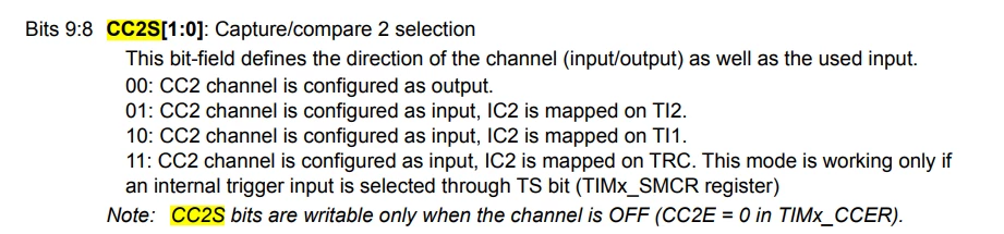
According to the CC2S bits description on the page 1354 of the RM0432, you have to write 10 on the CC2S bits so that the CC2 channel is configured as input and IC2 is mapped on TI1 (as mentioned on the description):

STTwo32_0-1711011524755.png

So, everything looks fine.

Best Regards.

STTwo-32


3 replies

b.a.
b.a.Author
Associate III
March 21, 2024
STTwo-32
STTwo-32Best answer
ST Technical Moderator
March 21, 2024

Hello @b.a. 

According to the CC2S bits description on the page 1354 of the RM0432, you have to write 10 on the CC2S bits so that the CC2 channel is configured as input and IC2 is mapped on TI1 (as mentioned on the description):

STTwo32_0-1711011524755.png

So, everything looks fine.

Best Regards.

STTwo-32


To give better visibility on the answered topics, please click on Accept as Solution on the reply which solved your issue or answered your question.
b.a.
b.a.Author
Associate III
March 21, 2024

yes, you are right!

I did not check but assumed the bit-meaning for CCS1 and CCS2 were identical, like they are for so many other registers... like CC2G just says refer to CC1G