Well, we traveled to the customer this week to see the issue and likely managed to solve it.
Our first suspection was some PLL jitter caused by some ringing on the power rails during arbitration.
Decreased the 2x120 Ohm pulls to reduce the current changes induced by the transceivers, but it had no effect on the issue.
We isolated the 5V supply of the CAN transceivers from the 3V3 feeding the MCU and it did not helped.
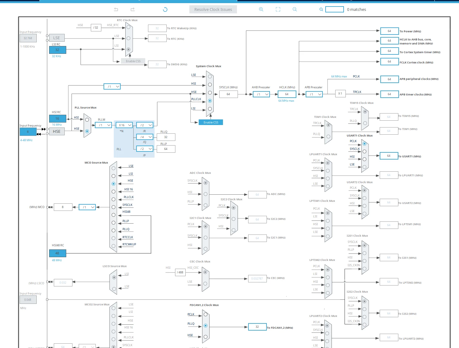
Then we monitored the PLL output fed to the CAN module on the MCO output and we did not seen any jitter so we abandoned the idea being clocking related.
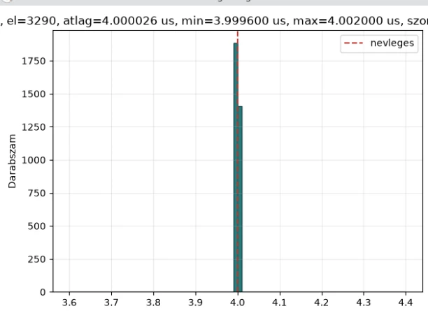
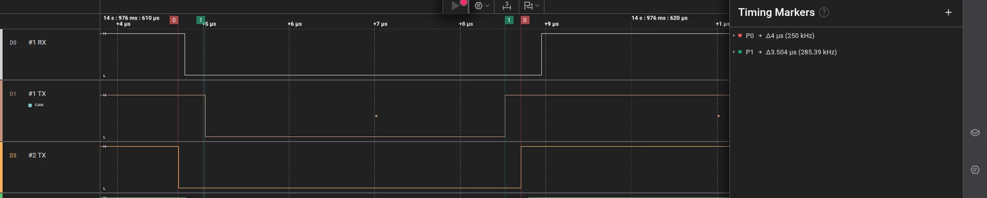
We made some scripting with the Saleae logic to see if the first node transmitting during arbitration ever fails to met the exact 4 us and no, it was always 4 us like this:
My instinct said if the shortened durations would be PLL glitch related then the first sensor waveform would be the most affected.
So seeing this an idea stuck into my mind: there is an open hardware design featuring the same MCU (in different package):
The firmware is also open source, but it turned out that the CAN bit timing parameters are calculated by the driver (only CAN clock and limitations are being reported upwards). Thankfully the Linux driver is open source and with some code following it turned out that the configuration for the same classic 250 kbaud CAN is slightly different than ours: they use 160 TQ instead of the 8 what we used.
Then guess what: increasing the TQ count to 160 solving the issue.
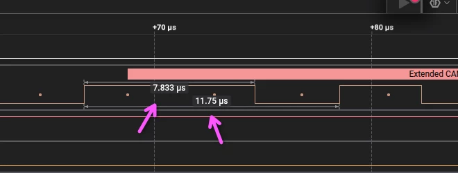
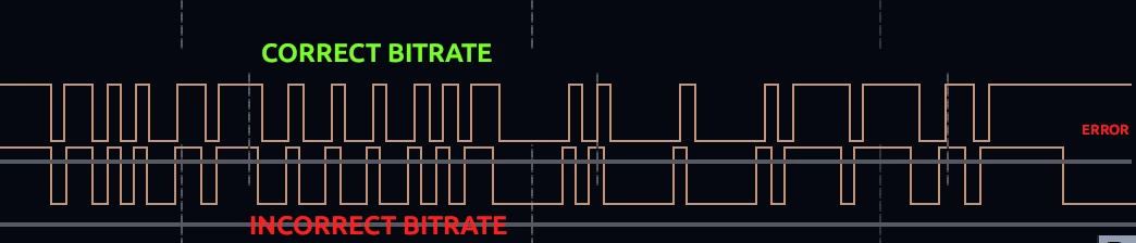
By reading some more general documentation on the CAN clock syncronisation it is likely that the compensations are limited to equal times of time quantas which was resulted too little resolution on compensation in our case:
Due to the resynchronization mechanism of CAN, if several parties start to transmit simultaneously, you can’t determine which of them is deviant and why, purely by observing the bus. You’d need to observe all participant’s Tx, simultaneously, too.
> Now it comes the next question: how to debug/fix this arbitration issue.
And what is the issue, exactly? Apart from what you see at the bus, what is it what made you to investigate this at all, what are the symptoms and how are they different from the expected?
Well, we traveled to the customer this week to see the issue and likely managed to solve it.
Our first suspection was some PLL jitter caused by some ringing on the power rails during arbitration.
Decreased the 2x120 Ohm pulls to reduce the current changes induced by the transceivers, but it had no effect on the issue.
We isolated the 5V supply of the CAN transceivers from the 3V3 feeding the MCU and it did not helped.
Then we monitored the PLL output fed to the CAN module on the MCO output and we did not seen any jitter so we abandoned the idea being clocking related.
We made some scripting with the Saleae logic to see if the first node transmitting during arbitration ever fails to met the exact 4 us and no, it was always 4 us like this:
My instinct said if the shortened durations would be PLL glitch related then the first sensor waveform would be the most affected.
So seeing this an idea stuck into my mind: there is an open hardware design featuring the same MCU (in different package):
The firmware is also open source, but it turned out that the CAN bit timing parameters are calculated by the driver (only CAN clock and limitations are being reported upwards). Thankfully the Linux driver is open source and with some code following it turned out that the configuration for the same classic 250 kbaud CAN is slightly different than ours: they use 160 TQ instead of the 8 what we used.
Then guess what: increasing the TQ count to 160 solving the issue.
By reading some more general documentation on the CAN clock syncronisation it is likely that the compensations are limited to equal times of time quantas which was resulted too little resolution on compensation in our case: