NUCLEO-L452RE-P current consumption way more than expected - ~ 20µA - 30µA in Shutdown Mode
- 3 replies
- 533 views
Hello everyone,
I am currently working with the NUCLEO-L452RE-P board and trying to evaluate its low-power performance.
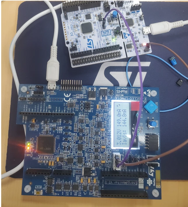
I am measuring the current consumption using jumper JP6 (IDD measurement point). The jumper is removed and a multimeter is connected in series.
My setup:
-
Board powered via ST-LINK USB (then power-cycled before measurement)
-
No external peripherals connected
-
All GPIOs configured as analog, no pull-up/pull-down
-
Debug set to "Serial Wire" (no trace)
-
No RTC or wake-up sources enabled
-
My code is as follows (I intentionally included the complete code to avoid missing any relevant detail):
/* USER CODE BEGIN Header */
/**
 ******************************************************************************
 * @file : main.c
 * @brief : Main program body
 ******************************************************************************
 * @attention
 *
 * Copyright (c) 2026 STMicroelectronics.
 * All rights reserved.
 *
 * This software is licensed under terms that can be found in the LICENSE file
 * in the root directory of this software component.
 * If no LICENSE file comes with this software, it is provided AS-IS.
 *
 ******************************************************************************
 */
/* USER CODE END Header */
/* Includes ------------------------------------------------------------------*/
#include "main.h"

/* Private includes ----------------------------------------------------------*/
/* USER CODE BEGIN Includes */

/* USER CODE END Includes */

/* Private typedef -----------------------------------------------------------*/
/* USER CODE BEGIN PTD */

/* USER CODE END PTD */

/* Private define ------------------------------------------------------------*/
/* USER CODE BEGIN PD */

/* USER CODE END PD */

/* Private macro -------------------------------------------------------------*/
/* USER CODE BEGIN PM */

/* USER CODE END PM */

/* Private variables ---------------------------------------------------------*/

/* USER CODE BEGIN PV */

/* USER CODE END PV */

/* Private function prototypes -----------------------------------------------*/
void SystemClock_Config(void);
static void MX_GPIO_Init(void);
/* USER CODE BEGIN PFP */

/* USER CODE END PFP */

/* Private user code ---------------------------------------------------------*/
/* USER CODE BEGIN 0 */

/* USER CODE END 0 */

/**
 * @brief The application entry point.
 * @retval int
 */
int main(void)
{

 /* USER CODE BEGIN 1 */

 /* USER CODE END 1 */

 /* MCU Configuration--------------------------------------------------------*/

 /* Reset of all peripherals, Initializes the Flash interface and the Systick. */
 HAL_Init();

 /* USER CODE BEGIN Init */

 /* USER CODE END Init */

 /* Configure the system clock */
 SystemClock_Config();

 /* USER CODE BEGIN SysInit */

 /* USER CODE END SysInit */

 /* Initialize all configured peripherals */
 MX_GPIO_Init();
 /* USER CODE BEGIN 2 */
 HAL_Delay(2000);
 HAL_PWREx_EnterSHUTDOWNMode();
 /* USER CODE END 2 */

 /* Infinite loop */
 /* USER CODE BEGIN WHILE */
 while (1)
 {
 /* USER CODE END WHILE */

 /* USER CODE BEGIN 3 */
 }
 /* USER CODE END 3 */
}

/**
 * @brief System Clock Configuration
 * @retval None
 */
void SystemClock_Config(void)
{
 RCC_OscInitTypeDef RCC_OscInitStruct = {0};
 RCC_ClkInitTypeDef RCC_ClkInitStruct = {0};

 /** Configure the main internal regulator output voltage
 */
 if (HAL_PWREx_ControlVoltageScaling(PWR_REGULATOR_VOLTAGE_SCALE2) != HAL_OK)
 {
 Error_Handler();
 }

 /** Initializes the RCC Oscillators according to the specified parameters
 * in the RCC_OscInitTypeDef structure.
 */
 RCC_OscInitStruct.OscillatorType = RCC_OSCILLATORTYPE_MSI;
 RCC_OscInitStruct.MSIState = RCC_MSI_ON;
 RCC_OscInitStruct.MSICalibrationValue = 0;
 RCC_OscInitStruct.MSIClockRange = RCC_MSIRANGE_8;
 RCC_OscInitStruct.PLL.PLLState = RCC_PLL_NONE;
 if (HAL_RCC_OscConfig(&RCC_OscInitStruct) != HAL_OK)
 {
 Error_Handler();
 }

 /** Initializes the CPU, AHB and APB buses clocks
 */
 RCC_ClkInitStruct.ClockType = RCC_CLOCKTYPE_HCLK|RCC_CLOCKTYPE_SYSCLK
 |RCC_CLOCKTYPE_PCLK1|RCC_CLOCKTYPE_PCLK2;
 RCC_ClkInitStruct.SYSCLKSource = RCC_SYSCLKSOURCE_MSI;
 RCC_ClkInitStruct.AHBCLKDivider = RCC_SYSCLK_DIV1;
 RCC_ClkInitStruct.APB1CLKDivider = RCC_HCLK_DIV1;
 RCC_ClkInitStruct.APB2CLKDivider = RCC_HCLK_DIV1;

 if (HAL_RCC_ClockConfig(&RCC_ClkInitStruct, FLASH_LATENCY_2) != HAL_OK)
 {
 Error_Handler();
 }
}

/**
 * @brief GPIO Initialization Function
 * @PAram None
 * @retval None
 */
static void MX_GPIO_Init(void)
{
 GPIO_InitTypeDef GPIO_InitStruct = {0};
 /* USER CODE BEGIN MX_GPIO_Init_1 */

 /* USER CODE END MX_GPIO_Init_1 */

 /* GPIO Ports Clock Enable */
 __HAL_RCC_GPIOC_CLK_ENABLE();
 __HAL_RCC_GPIOH_CLK_ENABLE();
 __HAL_RCC_GPIOA_CLK_ENABLE();
 __HAL_RCC_GPIOB_CLK_ENABLE();

 /*Configure GPIO pins : PC13 PC14 PC15 PC0
 PC1 PC2 PC3 PC4
 PC6 PC7 PC8 PC9
 PC10 PC11 PC12 */
 GPIO_InitStruct.Pin = GPIO_PIN_13|GPIO_PIN_14|GPIO_PIN_15|GPIO_PIN_0
 |GPIO_PIN_1|GPIO_PIN_2|GPIO_PIN_3|GPIO_PIN_4
 |GPIO_PIN_6|GPIO_PIN_7|GPIO_PIN_8|GPIO_PIN_9
 |GPIO_PIN_10|GPIO_PIN_11|GPIO_PIN_12;
 GPIO_InitStruct.Mode = GPIO_MODE_ANALOG;
 GPIO_InitStruct.Pull = GPIO_NOPULL;
 HAL_GPIO_Init(GPIOC, &GPIO_InitStruct);

 /*Configure GPIO pins : PH0 PH1 PH3 */
 GPIO_InitStruct.Pin = GPIO_PIN_0|GPIO_PIN_1|GPIO_PIN_3;
 GPIO_InitStruct.Mode = GPIO_MODE_ANALOG;
 GPIO_InitStruct.Pull = GPIO_NOPULL;
 HAL_GPIO_Init(GPIOH, &GPIO_InitStruct);

 /*Configure GPIO pins : PA0 PA1 PA2 PA3
 PA4 PA5 PA6 PA7
 PA8 PA9 PA10 PA11
 PA12 PA15 */
 GPIO_InitStruct.Pin = GPIO_PIN_0|GPIO_PIN_1|GPIO_PIN_2|GPIO_PIN_3
 |GPIO_PIN_4|GPIO_PIN_5|GPIO_PIN_6|GPIO_PIN_7
 |GPIO_PIN_8|GPIO_PIN_9|GPIO_PIN_10|GPIO_PIN_11
 |GPIO_PIN_12|GPIO_PIN_15;
 GPIO_InitStruct.Mode = GPIO_MODE_ANALOG;
 GPIO_InitStruct.Pull = GPIO_NOPULL;
 HAL_GPIO_Init(GPIOA, &GPIO_InitStruct);

 /*Configure GPIO pins : PB0 PB1 PB2 PB10
 PB11 PB12 PB13 PB14
 PB15 PB3 PB4 PB5
 PB6 PB7 PB8 PB9 */
 GPIO_InitStruct.Pin = GPIO_PIN_0|GPIO_PIN_1|GPIO_PIN_2|GPIO_PIN_10
 |GPIO_PIN_11|GPIO_PIN_12|GPIO_PIN_13|GPIO_PIN_14
 |GPIO_PIN_15|GPIO_PIN_3|GPIO_PIN_4|GPIO_PIN_5
 |GPIO_PIN_6|GPIO_PIN_7|GPIO_PIN_8|GPIO_PIN_9;
 GPIO_InitStruct.Mode = GPIO_MODE_ANALOG;
 GPIO_InitStruct.Pull = GPIO_NOPULL;
 HAL_GPIO_Init(GPIOB, &GPIO_InitStruct);

 /* USER CODE BEGIN MX_GPIO_Init_2 */

 /* USER CODE END MX_GPIO_Init_2 */
}

/* USER CODE BEGIN 4 */

/* USER CODE END 4 */

/**
 * @brief This function is executed in case of error occurrence.
 * @retval None
 */
void Error_Handler(void)
{
 /* USER CODE BEGIN Error_Handler_Debug */
 /* User can add his own implementation to report the HAL error return state */
 __disable_irq();
 while (1)
 {
 }
 /* USER CODE END Error_Handler_Debug */
}
#ifdef USE_FULL_ASSERT
/**
 * @brief Reports the name of the source file and the source line number
 * where the assert_param error has occurred.
 * @PAram file: pointer to the source file name
 * @PAram line: assert_param error line source number
 * @retval None
 */
void assert_failed(uint8_t *file, uint32_t line)
{
 /* USER CODE BEGIN 6 */
 /* User can add his own implementation to report the file name and line number,
 ex: printf("Wrong parameters value: file %s on line %d\r\n", file, line) */
 /* USER CODE END 6 */
}
#endif /* USE_FULL_ASSERT */
Expected behavior:
According to the datasheet, the STM32L452RE should consume in the range of ~67nA in Shutdown mode
Observed behavior:
I consistently measure around 20–30 µA on JP6 in Shutdown mode. The value is not perfectly stable and fluctuates.
Questions:
-
Is this expected behavior when using the NUCLEO-L452RE board?
-
Could the measured current be dominated by on-board components (e.g. level shifters, ST-LINK interface, SMPS, etc.) even when measuring at JP6?
-
What additional steps are required to measure the true MCU-only Shutdown current on this board?
I want to keep using the NUCLEO board if possible, but need to reduce the current significantly for a low power application
Any guidance or experience with accurate low-power measurements on this board would be greatly appreciated.
Thank you!
P.S.
I have also attached my .ioc file and a photo of my measurement setup
Edit: I observe approximately the same current consumption when using Stop2 mode which is very strange to me...