

Solved
Not able to send 8-bit data on SPI.
I am learning bare-metal programming on STM32F411RE (Nucleo board). I am trying to implement a SPI driver.
Even though I have set the Data Frame Format to 8-bit, My SCK consists of 16 clock cycles. Sending 8 bit data on this has weird behavior(I am trying to send 0x9D below):
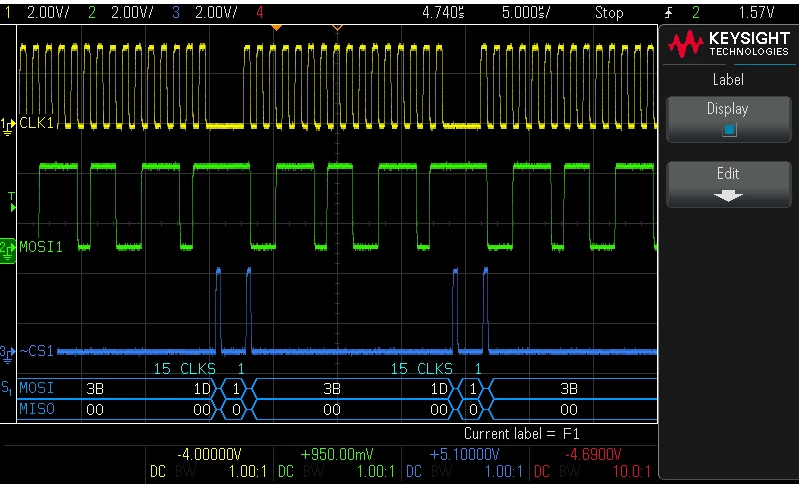
Here's my code:
#include "stm32f4xx.h" // Device header

void SPI1_init(void);
void SPI_write(uint8_t data);


int main()
{
	SPI1_init();

	GPIOA->BSRR = 1<<4;

	while(1)
	{
		GPIOA->BSRR = 1<<20;				//assert ~CS

		SPI_write(0x9D);
		//SPI_write(0xA2);

		GPIOA->BSRR = 1<<4;				//de-assert ~CS
	}

}


void SPI1_init(void)
{
	RCC->AHB1ENR |= 1;								//enable clock to PortA
	RCC->APB2ENR |= 1<<12;						//enable clock to SPI1

	GPIOA->MODER &= ~(3<<14 | 3<<10 | 3<<12 | 3<<8);		//clear SPI bits
	GPIOA->MODER |= (2<<10 | 2<<14 | 2<<12 | 1<<8 );	//set MOSI,MISO,SCK bits for AF and NSS as GPO

	GPIOA->AFR[0] &= ~(0xF<<20 | 0xF<<24 | 0xF<<28);			//clear AF
	GPIOA->AFR[0] |= (5<<20 | 5<<24 | 5<<28);			//setting AF05 for MOSI,MISO and SCK

	//SPI1->CR1 &= ~(1<<6);
	SPI1->CR1 = 0x31C;											//disable SPI, 8 bit, Master, Mode0 SPI
	//SPI1->CR1 &=~(1<<11);
	SPI1->CR2 |= 0;												//Motorola Frame format
	SPI1->CR1 |= 0x40;										//SPI enable

}


void SPI_write(uint8_t data)
{
	while(!(SPI1->SR & 0x2));		//till transmit buffer is NOT empty, do nothing.

	SPI1->DR = data;

	while(SPI1->SR & 0X80);		//while BSY flag is 1 do nothing. ie wait till transmission is complete

}
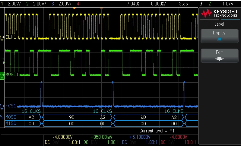
Sending 16 bit data, of-course, works perfectly (sending 0x9D and 0xA2 here):
My application requires me to send 24 bit data in a single ~CS cycle. So I can't use the 16-bit frame format. I need 8 bit frame format. Going through forum answers I found this answer trying to force the data register as:
*(__IO uint8_t *)&SPI->DR = data;
But even this doesn't work for me. I am still getting the 16 clock cycles on SCK. Any tips?
