


JP_ama
Associate III
July 20, 2023
Solved

Mysterious memory behaviour in simple DSP test program

Hello,

I am currently developing a DSP application on an STM32F439ZI Nucleo board in combination with a Pmod I2S2 audio codec board. So far, basic testing and filtering worked fine until I started to try FFT processing. I isolated the issue in a simple test program (code attached). I am using the CMSIS DSP library for the FFT and IFFT.

This is what the code does:

Audio sample data is transferred over I2S using DMA in circular mode. The DMA buffer itself is rather small in order to have the TxRxHalfComplete and TxRxComplete ISR called every time after one audio sample from the left and right channel has been received. I need this because I have an FIR filter function that needs to be called for every sample transmitted and received (tested and works, but not used inside the test program). Inside the ISRs the incoming samples are converted from 24 bit signed PCM into float32 and copied into a bigger circular input buffer. As soon as one half of the buffer is filled with data a flag is set. Inside the main while loop the sample block is then transformed into the frequency domain using arm_rfft_fast_f32 and immediately transformed back into the time domain. The output buffer's current index is delayed to ensure there is enough time to perform the FFT calculations (verified).

Here's the issue:

It works perfectly fine for a transform size of 1024 and 2048. If I make the transform / buffer size any larger or smaller the audio output gets corrupted. Output buffer delay is adjusted appropriately. On top you can see the 1 kHz sine wave that is fed into the unit, below that is the corrupted output of the left channel and below that is the output of the right channel (feeding samples straight though inside the ISR).
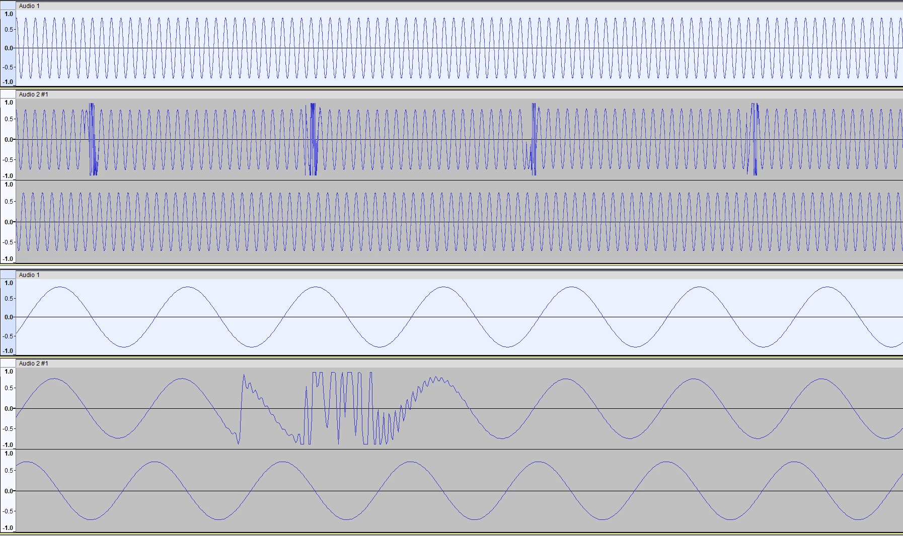
FFT.png

What I have already done trying to fix the bug:

I verified the FFT and IFFT is working correctly by feeding a known array with a known output into the transform functions - works.

Simply copying the input buffer to the output buffer in the while loop works as well.

The really weird thing is, if I simply uncomment line 155 where I memcpy just the input buffer into another totally unused buffer, that has nothing to do with the transform, it suddenly works for all transform sizes.


So I assume this must be some kind of memory access issue. However at this point I am absolutely clueless what could potentially cause this behavior or how I could debug it. I would highly appreciate if somebody could point me into the right direction!


Best regards

This topic has been closed for replies.
JP_ama
JP_amaBest answer
Associate III
July 25, 2023

I found the issue. The 20 - 30 us pre-delay looked very much like the time between two samples at 44.1 kHz sampling rate. This made me realize I was doing the FFT/IFFT one sample too early. The array index gets updated at the end of the TxRxHalfCplt ISR and I was setting the dataReady flag at the same time, which is wrong, because the new sample has not been written to the buffer yet. This actually happens in the following TxRxCplt ISR. So moving this piece of code from TxRxHalfCplt to TxRxCplt fixed it:


	if(currentInputBufferIndex == AUDIO_BUFFER_SIZE_HALF-1)
	{
		dataReady = 1;
		inputBufferOffset = 0;
		outputBufferOffset = AUDIO_BUFFER_SIZE_HALF;
	}

	if(currentInputBufferIndex == AUDIO_BUFFER_SIZE-1)
	{
		dataReady = 1;
		inputBufferOffset = AUDIO_BUFFER_SIZE_HALF;
		outputBufferOffset = 0;
	}


Thank you everyone for pointing me towards the solution!

20 replies

JP_ama
JP_amaAuthor
Associate III
July 21, 2023

Update: It is enough to just read from audioInputBuffer in the while loop before doing the FFT transform to make it work. No memcpy, nothing, just reading from it. If I don't do that, it's the same issue. What on earth is going on there?

Thanks!

Johi
Senior II
July 22, 2023

How does your design take into account cache coherency & data buffer alignment?

Johi_0-1690008487035.png


JP_ama
JP_amaAuthor
Associate III
July 22, 2023

It doesn't because I don't have to? I'm using an F4 which doesn't have a L1 cache. As far as I know it only has a D- and I-cache for flash memory access. Please correct me if I am wrong or if I didn't understand the concept.

The data buffer contains 32 bit floats. I double checked in the memory viewer during runtime that the buffers are aligned and not overlapping. I also checked for wrong array boundaries, but everything seems fine as well.

Thanks!

Johi
Senior II
July 22, 2023

@JP_ama, I am afraid you are correct and therefore I am not. Should have known as last week was investigating STM32F407 SDIO and therefore D-cache is flash only as stated in RM0090. Had some problems long time ago with STM32H735 where DMA did abnormal things from time to time related to cache coherency.

MM..1
Super User
July 22, 2023

Hi, in your code i dont see any time control. Any code on audio samples stream can work only if calculation speed > as stream speed. Seems your code with float calculations is slower and based on size of buffer corruption occurs on every N buf...

Simply your half and full calback copies dont endet fft arrays...

Too check volatile requirments for your defs. Array not volatile is optimized out maybe

JP_ama
JP_amaAuthor
Associate III
July 22, 2023

@MM..1 

The output buffer array index is running 512 samples behind the input buffer index (for 4096 transform size). That's about 11 ms. The FFT calculations take roughly 2 ms. I measured and verified this. Not sure if there are nicer ways to do this though.

I tried making the input buffer array volatile. However the volatile qualifier gets discarded in the arm_rfft_fast_f32 function call (compiler warning). So I'm not sure if this is doing much. But I am suspecting something like this causing the problem as well.

@Johi It makes perfect sense to investigate in this direction. I appreciate everyone taking the time to take a look into this. Thanks!

MM..1
Super User
July 23, 2023

Ok 2ms is one or both fft and this reflect to your graphs. In this 2ms you send to output intermediate calculations of fft instead real data, because you dont have time management. Too i recommend double output buffers swap...

Graduate II
July 23, 2023

Hello

Few notes with quick review:

Is it enough if you keep small delay instead of read from audioInputBuffer before FFT to get it working ?

I see you have USB, Eth, Usart initializations in yourt code. Is it possible that those have higher interrupt priority which delays I2S interrupts ? (the code is abbreviated i guess)

Then you init HAL_I2SEx_TransmitReceive_DMA with lenght of 4 but read buffer with lenght of 8. Is this considered to be this way ? (just note, im not familiar with I2S).

Br J.T

Piranha
Principal III
July 23, 2023

The inputBufferOffset, outputBufferOffset and dataReady are all modified in interrupt context and therefore are unsynchronized for the normal thread context (the main loop). As a quick fix - disable the interrupts while you read/modify the set of those variables. But eventually better redesign the logic using the principles from these articles:

https://ferrous-systems.com/blog/lock-free-ring-buffer/

https://www.snellman.net/blog/archive/2016-12-13-ring-buffers/

JP_ama
JP_amaAuthor
Associate III
July 24, 2023

@JTP1, size 4 as an argument is correct because it means the number of 24 bit (= 32 bit) data length. All the peripheral initializations are the standard ones for the nucleo board and are unused. However, you were right that adding a small delay instead of the read works as well. I need about 30 us for a transform length of 4096 samples. 

@MM..1I was wrong about the calculation time, this was for 1024/2048. For 4096 samples the FFT + IFFT takes 5,6 ms. I have a timeframe of 9 ms (512 samples). As I said 30 us pre-delay is enough but even adding 1 or 2 ms of delay works fine as well. So it's plenty of time to do the actual calculations.

So after all it seems to be a timing problem indeed. But I still do not understand why I need this pre-delay though. @Piranha I am already double buffering. When the dataReady flag is set, it takes 90 ms until the offset variables are modified again. I drew a small sketch of my buffer structure to visualize this. Where is the flaw in my thinking?

MM..1
Super User
July 25, 2023
 arm_rfft_fast_f32(&sMyFFTInstance, &audioInputBuffer[inputBufferOffset], fftBuffer, 0);
 arm_rfft_fast_f32(&sMyFFTInstance, fftBuffer, &audioOutputBuffer[outputBufferOffset], 1);

MM1_0-1690260764825.png

your info is in parenthes

JP_ama
JP_amaAuthor
Associate III
July 25, 2023

I am aware of that. But still, it is reading and modifying the half of the buffer, that is currently not written by DMA. So why is this a problem?

Thanks!

Piranha
Principal III
July 25, 2023

The last parameter of the HAL_I2SEx_TransmitReceive_DMA() function is the number of transfers, not item size. Also your buffers have 8 items, not 4. And overall running DMA on 4 samples is inefficient. Why aren't you running it on 2*4096 samples and then just processing the whole 4096 sample block at once in thread (non-interrupt) mode?

My previous post is about the fact that code is not interrupt-safe - the said tree variables are not protected in the main loop and an I2S/DMA interrupt can jump in and modify those at any moment. Magic delays will not solve this, you will have to learn the fundamental problem. Maybe start by reading this article and watching the related video:

https://www.embedded.com/programming-embedded-systems-race-conditions-and-how-to-avoid-them/

JP_ama
JP_amaAuthorBest answer
Associate III
July 25, 2023

I found the issue. The 20 - 30 us pre-delay looked very much like the time between two samples at 44.1 kHz sampling rate. This made me realize I was doing the FFT/IFFT one sample too early. The array index gets updated at the end of the TxRxHalfCplt ISR and I was setting the dataReady flag at the same time, which is wrong, because the new sample has not been written to the buffer yet. This actually happens in the following TxRxCplt ISR. So moving this piece of code from TxRxHalfCplt to TxRxCplt fixed it:


	if(currentInputBufferIndex == AUDIO_BUFFER_SIZE_HALF-1)
	{
		dataReady = 1;
		inputBufferOffset = 0;
		outputBufferOffset = AUDIO_BUFFER_SIZE_HALF;
	}

	if(currentInputBufferIndex == AUDIO_BUFFER_SIZE-1)
	{
		dataReady = 1;
		inputBufferOffset = AUDIO_BUFFER_SIZE_HALF;
		outputBufferOffset = 0;
	}


Thank you everyone for pointing me towards the solution!

RhSilicon
Lead
July 27, 2023

(Maybe it's some starting point (the TxRxHalfCplt ISR) for making the Ghostbusters tools :grinning_face_with_sweat:)

Piranha
Principal III
July 25, 2023

The last parameter of the HAL_I2SEx_TransmitReceive_DMA() function is the number of transfers, not item size. Also your buffer arrays have 8 items, not 4 like in parameter. And overall running DMA on 4 samples is inefficient. Why aren't you running it on 2*4096 samples and then just processing the whole 4096 sample block at once in thread (non-interrupt) mode?

My previous post is about the fact that code is not interrupt-safe - the said tree variables are not protected in the main loop and an I2S/DMA interrupt can jump in and modify those at any moment. Think about the consequences of interrupt, which modifies those three variables, executing, for example, between the arm_rfft_fast_f32arm_rfft_fast_f32() calls. Even, if it doesn't happen now, it is a disaster waiting to happen. Magic delays will also not solve this, one has to learn the fundamental problem. Maybe start by reading this article and watching the related video.

The solution for this is actually pretty simple. The general principle is explained in the previous links about the lock-free ring buffer. In this case you can just think of it as a buffer of a length of two.

volatile bool iSet, iGet;

void ISR(void)
{
	// The next buffer is ready
	iSet = !iSet;
}

int main(void)
{
	for (;;) {
		bool iBuf = iGet;
		if (iBuf != iSet) {
			ProcessData(&aanBuffers[iBuf]);
			iGet = !iBuf;
		}
	}
}

All the other indexes, pointers etc. can and must be calculated from these critical variables. Such code is interrupt-safe, much simpler and is the most efficient solution.

JP_ama
JP_amaAuthor
Associate III
July 26, 2023

Yes, and I think it needs to be 4 because on the F439 it's a 16 bit peripheral operating in 32 bit mode (because I am using a 24 bit audio codec). It should be possible to switch DMA from half-word to word transfer though.

I answered the question why I am not doing 4096 sample block DMA transfers in my initial post. I need to filter the incoming samples with a direct FIR filter. This filter function needs to be called for every incoming sample. That's why I am calling it inside the ISRs. This function is not shown in my code because I wanted to create a test program that is as simple as possible to illustrate my issue. The direct FIR filter already worked and I though it would be unnecessarily confusing to include it. Do you think there is another way to do this more efficiently?

I have to switch over to implementing it in a FreeRTOS task anyways. I am going to include and implement all the suggestions you made. Any thoughts on using xTaskNotifyFromISR to wake up the task when data is ready to be processed?

Thanks!

Piranha
Principal III
July 27, 2023

Oh, indeed it's a 16-bit peripheral. Anyway, let's improve some of your previous code...

// Force the shift operations to at least 32-bit unsigned
lSample = (rxBuffer[0] << 8ul) | (rxBuffer[1] >> 8ul);
lSample |= (rxBuffer[0] & 0x8000) ? 0xFF000000 : 0x00000000;

// Improve the sign extension
lSample = (rxBuffer[0] << 8ul) | (rxBuffer[1] >> 8ul);
lSample = (int32_t)(lSample << 8ul) >> (int32_t)8;

// Incorporate the sign extension left shift into the halfword combining
lSample = (rxBuffer[0] << 16ul) | rxBuffer[1];
lSample = (int32_t)lSample >> (int32_t)8;

// Merge the code lines
lSample = (int32_t)((rxBuffer[0] << 16ul) | rxBuffer[1]) >> (int32_t)8;

// Use a single 32-bit load and ARM specific instructions
lSample = (int32_t)__REV(__REV16(*(uint32_t*)&rxBuffer[0])) >> (int32_t)8;

For 32-bit loads the uint32_t buffer array type would not need a pointer cast and will perform better, because it's inherently aligned to 4 bytes. The DMA can still do 16-bit transfers, if 32-bit is not possible.

The big question is why you are not using the SAI peripheral? It is a much more versatile and simpler to use peripheral for this purpose.


This filter function needs to be called for every incoming sample.

Why cannot you just capture the whole block and do all processing in thread mode, including the FIR filtering? The only valid argument would be some strict real-time requirements for some other functionality.

Actually in my previous code it would be better not to invert the iSet variable in ISR, but set it to true/false explicitly, depending on half/full or first/second DMA buffer interrupt. That will ensure that it always recovers correctly even if the ISR is delayed for prolonged time. With RTOS the general principles are the same, but typically you can eliminate the iGet variable, because the reception of the notification itself already means that there is a new buffer to process and you don't need additional testing for that. And, if you use the DMA in dual buffer mode, then the absolute fastest way to save "iSet" is to just save the contents of DMA_CR register in ISR and get the buffer index from the DMA_SxCR_CT bit in thread mode. Just take a note that, when the ISR executes, that bit shows the new buffer, which the DMA is already processing at that moment.

JP_ama
JP_amaAuthor
Associate III
August 1, 2023

Your assumption is correct. I cannot capture whole blocks because it's going to be a real-time (nearly) zero delay application. There will be smaller FFT transforms as well, just testing the largest cases now to verify the fundamentals are working correctly.

Okay, so here's what I got right now. Works perfectly fine. However, as soon as I take this over into a FreeRTOS context, I get thrown into the HardFault_Handler with PRECISERR set. If I choose a smaller transform size than 4096 it works fine as well. All buffers are allocated statically and not on the FreeRTOS heap or inside the task. Any ideas what the issue could be?

Also I realized I have to introduce another magic delay before doing the FFT because otherwise the direct FIR filtering will read wrong data (because the the FFT modifies the input buffer). I am not really convinced the way I am handling this is smart. I can't just copy the buffers all the time because it's a waste of processing power and I won't have enough RAM to do that as soon as the whole algorithm is running with multiple tasks / instances.

The modulo operations inside the direct FIR filter function are probably stupid but I don't know of any other ways to make the buffer wrap around backwards.

I appreciate all suggestions how to change the structure of the buffering!

Thanks.