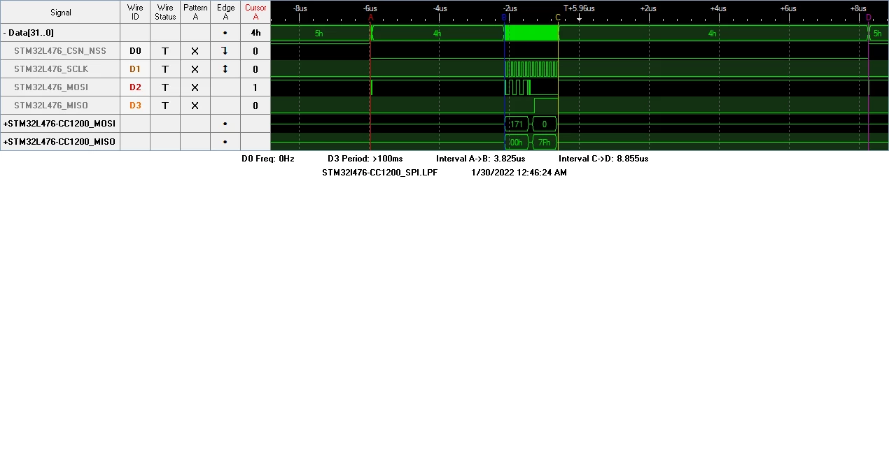
Make SPI NSS hardware output produce a steady low during SPI transaction
Is there a way to make SPI NSS hardware output produce a steady state low without NSSP during SPI transaction without manual config and toggle of CSN GPIO?
Interface of STM32L476RG to TI CC1200 SPI. Using MCU registers with NSS produces short acceptable CSN to clock start interval but I cannot get rid of the high pulse between frames which causes the CC1200 to malfunction. Manually configuring and toggling The CSN GPIO produces an unacceptably long delay between start of CSN low and start of SPI clock pulses but transactions work. My project requires optimized SPI transaction speed as there are many seperate 2 byte transactions that need to take place in as short a duration as possible. Inserting the CSN toggle into the HAL_SPI_TransmitReceive_IT or HAL_SPI_TransmitReceive functions shortens the duration between CSN-clock and visa versa but still adds significantly longer interval than the HAL NSS hardware output. 2 byte transactions are significantly longer than necessary.
Section 42.4.5 of the HAL STM32l476 user manual states the following-
“Hardware NSS management (SSM = 0): in this case, there are two possible configurations. The configuration used depends on the NSS output configuration (SSOE bit in register SPIx_CR1).
– NSS output enable (SSM=0,SSOE = 1): this configuration is only used when the MCU is set as master. The NSS pin is managed by the hardware. The NSS signal is driven low as soon as the SPI is enabled in master mode (SPE=1), and is kept low until the SPI is disabled (SPE =0). A pulse can be generated between continuous communications if NSS pulse mode is activated (NSSP=1). The SPI cannot work in multimaster configuration with this NSS setting.
– NSS output disable (SSM=0, SSOE = 0): if the microcontroller is acting as the master on the bus, this configuration allows multimaster capability. If the NSS pin is pulled low in this mode, the SPI enters master mode fault state and the device is automatically reconfigured in slave mode. In slave mode, the NSS pin works as a standard “chip select�? input and the slave is selected while NSS line is at low level.�?
Above implies that the below initialization will produce a NSS/CSN low with a pulse between frames. Which it does.
hspi2.Instance = SPI2;
hspi2.Init.Mode = SPI_MODE_MASTER;
hspi2.Init.Direction = SPI_DIRECTION_2LINES;
hspi2.Init.DataSize = SPI_DATASIZE_8BIT;
hspi2.Init.CLKPolarity = SPI_POLARITY_LOW;
hspi2.Init.CLKPhase = SPI_PHASE_1EDGE;
hspi2.Init.NSS = SPI_NSS_HARD_OUTPUT;
hspi2.Init.BaudRatePrescaler = SPI_BAUDRATEPRESCALER_8;
hspi2.Init.FirstBit = SPI_FIRSTBIT_MSB;
hspi2.Init.TIMode = SPI_TIMODE_DISABLE;
hspi2.Init.CRCCalculation = SPI_CRCCALCULATION_DISABLE;
hspi2.Init.CRCPolynomial = 7;
hspi2.Init.CRCLength = SPI_CRC_LENGTH_DATASIZE;
hspi2.Init.NSSPMode = SPI_NSS_PULSE_ENABLED;
Registers after Init:
CR1=0x11c
CR2=0x170c
NSS hardware output with NSSP enabled
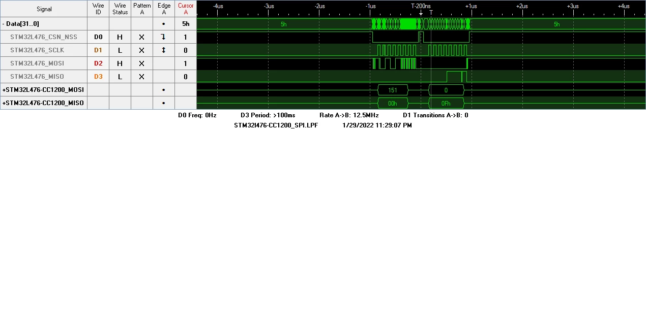
And implies that the below initialization will produce a NSS/CSN low without a pulse between frames. Which it does not.
hspi2.Instance = SPI2;
hspi2.Init.Mode = SPI_MODE_MASTER;
hspi2.Init.Direction = SPI_DIRECTION_2LINES;
hspi2.Init.DataSize = SPI_DATASIZE_8BIT;
hspi2.Init.CLKPolarity = SPI_POLARITY_LOW;
hspi2.Init.CLKPhase = SPI_PHASE_1EDGE;
hspi2.Init.NSS = SPI_NSS_HARD_OUTPUT;
hspi2.Init.BaudRatePrescaler = SPI_BAUDRATEPRESCALER_8;
hspi2.Init.FirstBit = SPI_FIRSTBIT_MSB;
hspi2.Init.TIMode = SPI_TIMODE_DISABLE;
hspi2.Init.CRCCalculation = SPI_CRCCALCULATION_DISABLE;
hspi2.Init.CRCPolynomial = 7;
hspi2.Init.CRCLength = SPI_CRC_LENGTH_DATASIZE;
hspi2.Init.NSSPMode = SPI_NSS_PULSE_DISABLED;
Registers after Init:
CR1=0x11c
CR2=0x1704
NSS hardware output with NSSP disabled
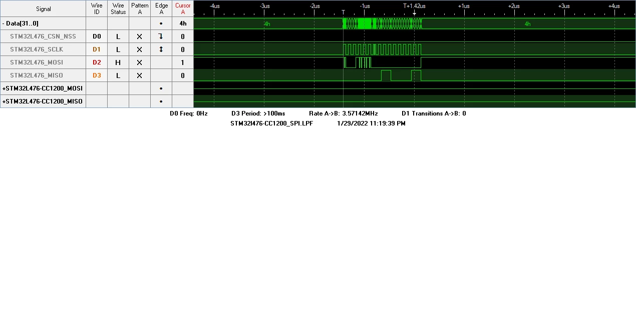 Manual Toggle