


LucasStartTech
Associate III
March 27, 2025
Question

LCD TFT 40 Pins

  • March 27, 2025
  • 2 replies
  • 1619 views

@mƎALLEm @TDK @Andrew Neil 

Hi! I am trying to drive a 40 pins TFT screen by myself, but it's been a little difficult to achieve this. 

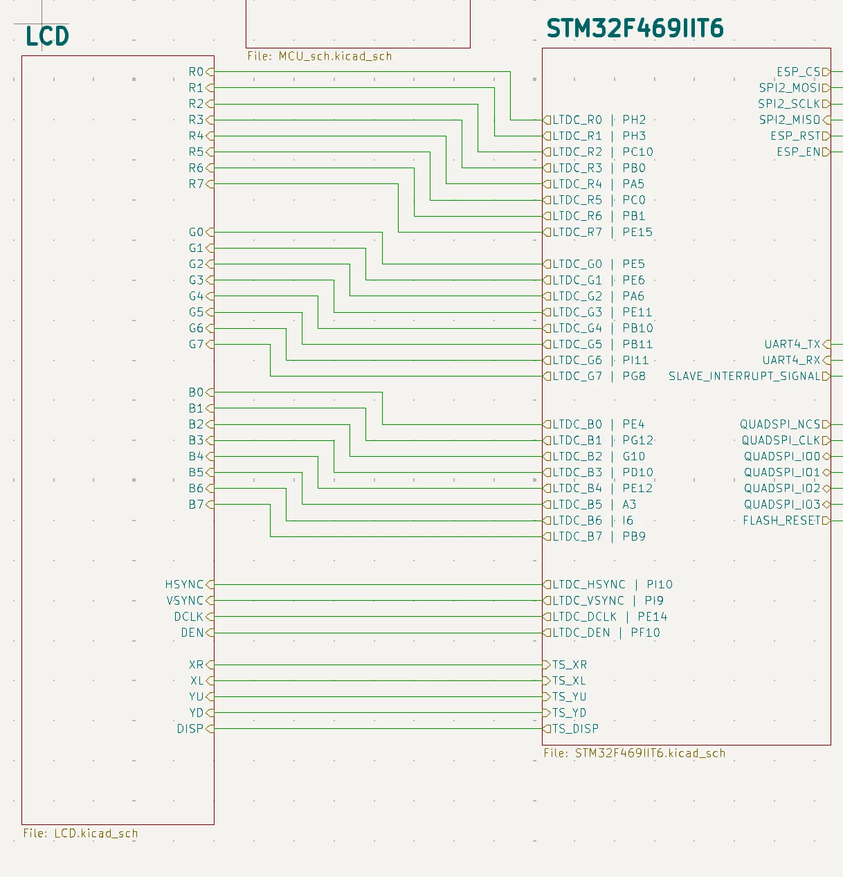
First -> I did this schematic to connect the screen to my microcontroller:
 

LucasStartTech_1-1743075416918.png

I thought it would work fine, since I was able to turn the back lights on (even though it is a separe circuit), and to turn it on and off using the DISP I/O.

To teste it, I configured the LTDC feature of my STM32 and sent only the background color, to make things easier, since I wanted to see a change in the screen as a first step only. I detected the correct data being sent using a logic analyzer and yet, I got no changes in the screen at all, while I was expecting to have some change, even a random one.

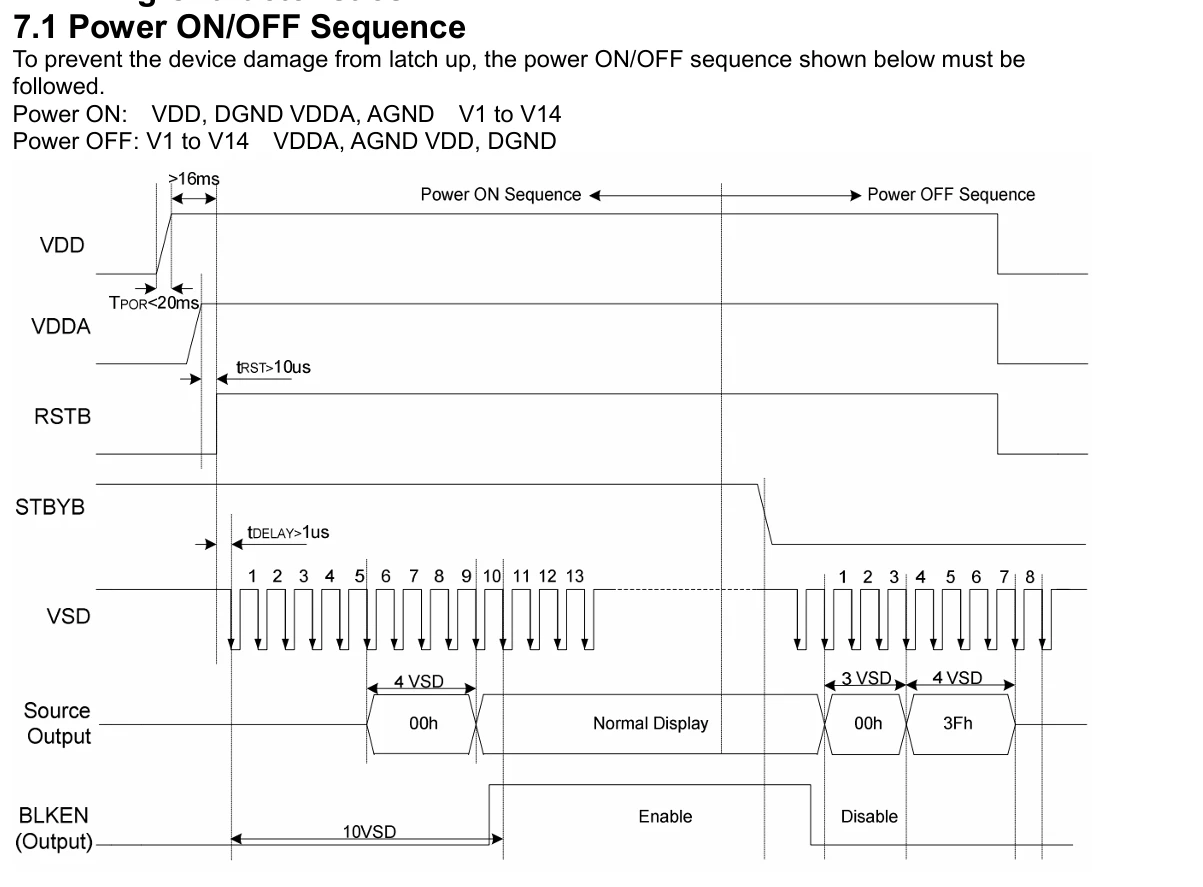
Second -> Reading through the datasheet I've found a timing diagram for a power ON/OFF sequence. 
LucasStartTech_2-1743075502219.png


However, I cannot detect in the 40 pins pinout such pins as VDDA, RSTB, STBYB and VSD.
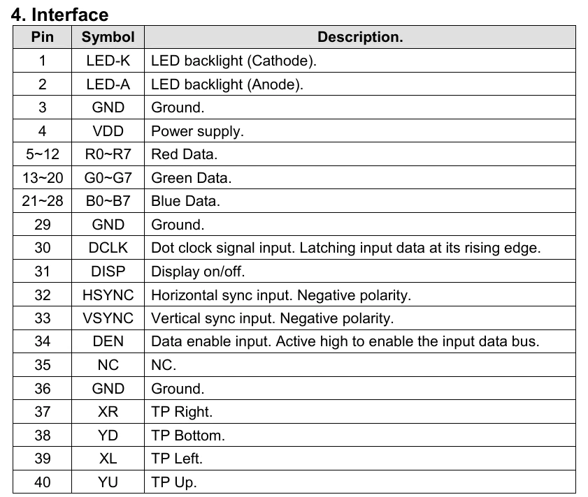
LucasStartTech_3-1743075553567.png

Given the searches I've made, seems like not following this sequence, the screen will not operate normally, which would explain why my background color does not appear. (Am I thinking straight?)

Does someone know how to do this?

Thank you!


This topic has been closed for replies.

2 replies

Amel NASRI
ST Technical Moderator
April 4, 2025

Hi @LucasStartTech ,

The application note AN4861: Introduction to LCD-TFT display controller (LTDC) on STM32 MCUs, highlights that some additional signals not part of the LTDC signals may be included in some display panel interfaces.

The LTDC provides up to 28 signals using simple 3.3 V signaling including:
• Pixel clock LCD_CLK
• Data enable LCD_DE
• Synchronization signals (LCD_HSYNC and LCD_VSYNC)
• Pixel data RGB888
In the same application note, you can find some recommendations on how to manage the additional signals:

  • These additional signals are required for a display module to be fully functional. 
  • The signals that are not part of the LTDC, may be managed using GPIOs and other peripherals and may need
    specific circuits.

Please refer to the mentioned application note for detailed information on configuring the LTDC peripheral. This includes hardware and pin configurations as well as application examples.

-Amel

To give better visibility on the answered topics, please click on "Best Answer" on the reply which solved your issue or answered your question.
Tesla DeLorean
Guru
April 4, 2025

Link to the specific data sheet for the display you're talking about.

The Vendor should be able to explain the pins exported, and which of signals relate to the panel or controller are managed at the interface presented to you.

Tips, Buy me a coffee, or three.. PayPal Venmo (See Profile) Up vote any posts that you find helpful, it shows what's working..