

Abhishek Deouskar
Associate III
July 2, 2018
Solved

Issues in changing baudrate of USART1 on the fly

  • July 2, 2018
  • 13 replies
  • 2300 views
Posted on July 02, 2018 at 11:00

Hello,

I am using an STM32F042 controller. I have to send a wake-up pattern followed immediately by 5 bytes (@10400 baud) from my device. 

Wakeup pattern: 25msec LOW followed by 25msec HIGH

5 byte sequence: 0xC1, 0x11, 0xF1, 0x81, 0x44

I tried the following: 

1) I configured the GPIOA, Pin 10, created a delay function and sent the Wakeup pattern. However, I am facing difficulties reconfiguring the GPIO into the USART Mode on the fly and then transmitting the 5-byte sequence.

GPIO_ResetBits(GPIOA, GPIO_Pin_10);

delay_nMSEC(25);

GPIO_SetBits(GPIOA, GPIO_Pin_10);

delay_nMSEC(25);

usart1_init(10400);

USART_SendData(USART1, 0xC1);

while(((USART1->ISR & USART_ISR_TXE) && (USART1->ISR & USART_ISR_TC)) == 0){}

The above code does not work. I get the wakeup pattern correctly and then a single pulse of roughly 5msec after that. But no 0xC1. However, if I put the

USART_SendData(USART1, 0xC1);

in a while(1) loop, I get data transmission correctly. However, I need to transmit it only once. 

2) I sent the wake-up pattern in USART mode at 200 baud (SysClock is 8Mhz) and then tried to reconfigure the frequency to 10400 baud, but no data is transmitted after reconfiguration as well. 

usart1_init(200);   //FOr 8Mhz, 0xF0 at 200 baud is 25msec LOW and 25msec HIGH

USART_SendData(USART1, 0xF0);

while(((USART1->ISR & USART_ISR_TXE) && (USART1->ISR & USART_ISR_TC)) == 0){}

usart1_init(10400);

USART_SendData(USART1, 0xC1);

while(((USART1->ISR & USART_ISR_TXE) && (USART1->ISR & USART_ISR_TC)) == 0){}

Here too, the wake-up sequence is correctly transmitted, but not the following transmission. 

PS: The USART1 configuration below is correct as it has been independently tested. Also the delay_mSec function works correctly. I have verified the same on a DSO.

Here are some of the functions I have used:

void usart1_init(int baudrate)

{

   GPIO_DeInit(GPIOA);

   GPIO_InitTypeDef GPIO_InitStruct;

   RCC_AHBPeriphClockCmd(RCC_AHBPeriph_GPIOA, ENABLE);

   GPIO_InitStruct.GPIO_Pin = GPIO_Pin_9;

   GPIO_InitStruct.GPIO_Mode = GPIO_Mode_AF;

   GPIO_InitStruct.GPIO_Speed = GPIO_Speed_50MHz;

   GPIO_InitStruct.GPIO_OType = GPIO_OType_PP;

   GPIO_InitStruct.GPIO_PuPd = GPIO_PuPd_NOPULL;

   GPIO_Init(GPIOA, &GPIO_InitStruct);

   GPIO_InitStruct.GPIO_Pin = GPIO_Pin_10;

   GPIO_InitStruct.GPIO_Mode = GPIO_Mode_AF;

   GPIO_InitStruct.GPIO_Speed = GPIO_Speed_50MHz;

   GPIO_InitStruct.GPIO_OType = GPIO_OType_OD;

   GPIO_InitStruct.GPIO_PuPd = GPIO_PuPd_UP;

   GPIO_Init(GPIOA, &GPIO_InitStruct);

   GPIO_PinAFConfig(GPIOA, GPIO_PinSource10, GPIO_AF_1);

   GPIO_PinAFConfig(GPIOA, GPIO_PinSource9, GPIO_AF_1);


   USART_Cmd(USART1, DISABLE);

   USART_InitTypeDef USART_InitStruct;

   RCC_APB2PeriphClockCmd(RCC_APB2Periph_USART1, ENABLE);


   USART_InitStruct.USART_BaudRate = baudrate;

   USART_InitStruct.USART_WordLength = USART_WordLength_8b;

   USART_InitStruct.USART_StopBits = USART_StopBits_1;

   USART_InitStruct.USART_Parity = USART_Parity_No;

   USART_InitStruct.USART_HardwareFlowControl = USART_HardwareFlowControl_None;

   USART_InitStruct.USART_Mode = USART_Mode_Tx | USART_Mode_Rx;

   USART_Init(USART1, &USART_InitStruct);

   NVIC_InitTypeDef NVIC_InitStructure;

   NVIC_InitStructure.NVIC_IRQChannel = USART1_IRQn;

   NVIC_InitStructure.NVIC_IRQChannelPriority = 0;

   NVIC_InitStructure.NVIC_IRQChannelCmd = ENABLE;

   NVIC_Init(&NVIC_InitStructure);

   /*Swap Rx and Tx Pins*/   

   USART_SWAPPinCmd(USART1, ENABLE);

   USART_ITConfig(USART1, USART_IT_RXNE, DISABLE);

   USART_Cmd(USART1, ENABLE);

}

void TIM16_IRQHandler(void)

{

   if(TIM_GetITStatus(TIM16,TIM_IT_Update))

   {

      TIM_ClearITPendingBit (TIM16, TIM_IT_Update);

      TIM_Cmd(TIM16, DISABLE);

      overflow_delaynMSEC = 1;

   }

}

void delay_nMSEC(int miliseconds)

{

   overflow_delaynMSEC = 0;

   TIM_Cmd(TIM16, DISABLE);

   TIM_SetAutoreload(TIM16, miliseconds*79);

   TIM_SetCounter (TIM16, 0);

   TIM_Cmd(TIM16, ENABLE);


   while(overflow_delaynMSEC == 0){}

   overflow_delaynMSEC = 0;

}

#usart1 #gpio-remap #baudrate-change #reconfigure #usart-speed #on-the-fly #gpio #stm32f042

This topic has been closed for replies.
Best answer by Abhishek Deouskar

Posted on July 09, 2018 at 14:48


Waclawek.Jan

? and

Turvey.Clive.002

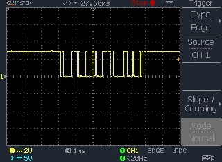
? -  Thank You for your responses. My issue was that my DSO was not capturing the bytes when it was the 250ms or higher scale. When I enabled edge-triggering on my DSO at 1ms scale, the data was captured perfectly. So the original code I gave out worked. 


13 replies

waclawek.jan
Super User
July 2, 2018
Posted on July 02, 2018 at 22:54

You can init USART beforehand. All you need to do is then is to change the Tx pin from AF to Out in GPIOx_MODER for the wakeup pulse, and then change it back from Out to AF. Nothing else.

Look up the GPIOx_MODER register in the GPIO chapter of Reference Manual.

JW

Abhishek Deouskar
Associate III
July 3, 2018

Posted on July 03, 2018 at 11:42


Waclawek.Jan

? - 

I tried the following piece of code:

timer16_config()


usart1_init(10400)

GPIOA-&gtMODER &= ~(GPIO_MODER_MODER0 << (0x0A * 2))          //Clear previous config of MODER


GPIOA-&gtMODER |= (((uint32_t)0x01) << (0x0A * 2))          //Set MODER register to OUT mode

//Wakeup Pattern


GPIO_ResetBits(GPIOA, GPIO_Pin_10)


delay_nMSEC(25)


GPIO_SetBits(GPIOA, GPIO_Pin_10)


delay_nMSEC(25)

GPIOA-&gtMODER &= ~(GPIO_MODER_MODER0 << (0x0A * 2))       //Clear previous config of MODER


GPIOA-&gtMODER |= (((uint32_t)0x02) << (0x0A * 2))          //Set MODER register to AF mode

USART1-&gtCR1 |= USART_CR1_UE //Enable USART1

USART_SendData(USART1, 0xC1)


while(((USART1-&gtISR & USART_ISR_TXE) && (USART1-&gtISR & USART_ISR_TC)) == 0){}


The above is the response I got on DSO. 

If say, I repeat the SendData command to the code, 

USART_SendData(USART1, 0xC1)


while(((USART1-&gtISR & USART_ISR_TXE) && (USART1-&gtISR & USART_ISR_TC)) == 0){}

USART_SendData(USART1, 0xC1)


while(((USART1-&gtISR & USART_ISR_TXE) && (USART1-&gtISR & USART_ISR_TC)) == 0){}

I end up with this:


If I add the USART_SendData command to a while(1) loop, I eventually get my sequence, but that is after at least 100msecs


Eventually, after some time has passed: 
 

Instead of the custom Hardware I have been using, I also tried a translated version of the code on my STM32F3 Discovery. I get the same response.


waclawek.jan
Super User
July 3, 2018

Posted on July 03, 2018 at 13:25


and
 

are clearly taken at different IO setting (or very different scope setting/external circuitry), given the edges/slope.

It's hard to discuss a moving target.

   GPIO_InitStruct.GPIO_Pin = GPIO_Pin_10;


   GPIO_InitStruct.GPIO_Mode = GPIO_Mode_AF;


   GPIO_InitStruct.GPIO_Speed = GPIO_Speed_50MHz;


   GPIO_InitStruct.GPIO_OType = GPIO_OType_OD;


   GPIO_InitStruct.GPIO_PuPd = GPIO_PuPd_UP;


   GPIO_Init(GPIOA, &GPIO_InitStruct);

OD and internal pullup alone is a suspicious combination.

JW

Tesla DeLorean
Guru
July 3, 2018
Posted on July 03, 2018 at 12:41

Check that TXE is high before sending data

Check that TC goes high, and make sure you clear it, to determine when the last bit hits the wire.

Tips, Buy me a coffee, or three.. PayPal Venmo (See Profile) Up vote any posts that you find helpful, it shows what's working..
Abhishek Deouskar
Associate III
July 6, 2018
Posted on July 06, 2018 at 13:30

Turvey.Clive.002

- I tried this. I set the TCCF to clear the TC flag, but it did not work. I also checked for TXE before sending data. 

I am pondering over a different approach:

PA10 pin has TIM1_CH3 also as an AF. Could I use this to create PWM output with a variable duty cycle? I was thinking of using a baud rate of 10400*9 = 93600 because at the max I can have 9 ones or 9 zeros in a sequence (including start and stop bits). My question to you is this, Will it work?

Abhishek Deouskar
Abhishek DeouskarAuthorBest answer
Associate III
July 9, 2018

Posted on July 09, 2018 at 14:48


Waclawek.Jan

? and

Turvey.Clive.002

? -  Thank You for your responses. My issue was that my DSO was not capturing the bytes when it was the 250ms or higher scale. When I enabled edge-triggering on my DSO at 1ms scale, the data was captured perfectly. So the original code I gave out worked. 


waclawek.jan
Super User
July 9, 2018
Posted on July 09, 2018 at 17:38

Ah, that explains it.

Thanks for coming back with the result.

Can you please tag your last post as 'Correct' so that that it can be seen that issue was resolved.

JW

AL.8
Visitor II
March 22, 2020

To change the baud rate on the fly, you need to wait for the completion of the transmission and reception of UART.

To do this, in the functions HAL_UART_RxCpltCallback and HAL_UART_TxCpltCallback set your completion flags.

Next, wait for the completion of reception / transmission. then switch the baud rate.

void setBaudRate (uint32_t br)

{

uint32_t pclk = HAL_RCC_GetPCLK1Freq ();

huart4.Instance-> BRR = UART_BRR_SAMPLING16 (pclk, huart4.Init.BaudRate = br);

}

Do not prohibit or allow UART in the body of this function! Tested on STM32F103VE.