

Associate II
August 1, 2026
Solved

Is this schematic right regarding the ADC clock for STM32G4xx MCUs?

  • August 1, 2026
  • 12 replies
  • 182 views

I have used some time to figure out to use the ADCs for a couple of Nucleo STM32G4xx boards. In particular I liked to be able to make use of the asynchronous clock. I found out by some trials and errors to get the right RCC settings for that.

In RM0440 you got a ADC clock schematic figure 83 page 597. I have tried to enlarge this schematic a bit regarding the RCC controls like this:
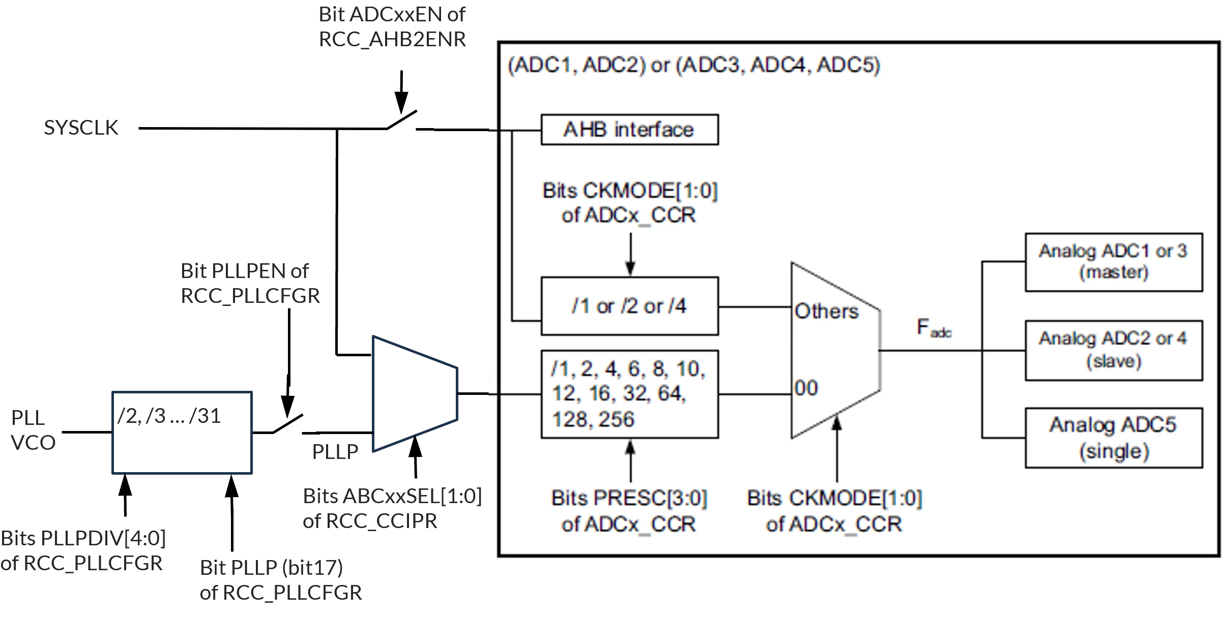


Can you agree to this schematic?

These functions can help configure RCC for the other ADC clock input:

__HAL_RCC_ADC12_CLK_ENABLE()         Enables clock to AHB interface
__HAL_RCC_PLLCLKOUT_ENABLE(RCC_PLL_ADCCLK); Enables clock to PLLP

I did not find a function outside the big HAL RCC init data structure to set the bits ABCxxSEL[1:0] of RCC_CCIPR, so I did that bare metal.

 

Best answer by AScha.3

So…

>I am new here and to these STM32 processors

maybe you should ask : how to use this and the CubeIDE and what you want to do …

I wrote in the beginning: you can set the clock for ADC in CubeMX - so why not just doing it ? 

Or is it just to find out something in the internal structure of a soc , thats only valid for exactly this version ? why ?

OHhhh - i just see, you playing with Arduino, ok, now i understand better, why you ask.

 + in Arduino you cannot control these kind of chips anyway (i know, because i tried...), you can get in the best-case scenario a dont-know-why-it-works-now mix of simple Arduino commands and HAL-library snippets.

Just believe me: Arduino is perfect to get something running in view minutes, if a good library doing, what you want.

But if you want something, thats not covered by ready made libs and functions, and want/need go to the limits that such a complex SOC (not just cpu, its a System On Chip)  you have to use the tool of the manufacturer , here STM .

​​​​​​​ + so finally about your first question: yes, your schematic looks ok . :)

12 replies

AScha.3
Super User
August 1, 2026

It should be easy to set in Cube :


If you feel a post has answered your question, please click on " Best Answer ".
MasterT
Lead II
August 1, 2026

See in RCCex

  RCC_PeriphCLKInitTypeDef PeriphClkInit  = {0};

PeriphClkInit.PeriphClockSelection = RCC_PERIPHCLK_ADC12;
//PeriphClkInit.Adc12ClockSelection = RCC_ADC12CLKSOURCE_SYSCLK;
PeriphClkInit.Adc12ClockSelection = RCC_ADC12CLKSOURCE_PLL;
if (HAL_RCCEx_PeriphCLKConfig(&PeriphClkInit) != HAL_OK)
{
Error_Handler();
}

PLL has to be configured before adc starts.


BackflipAuthor
Associate II
August 1, 2026

When you use HAL_RCCEx_PeriphCLKConfig(), then it sets almost everything in the rather complicated RCC. In order to set the PLL parameters, the PLL is disabled for some time, while system clock is switched to another source. That is why I looked for a solution outside the use of the RCC hal datastructure, RCC_PeriphCLKInitTypeDef.

At the moment I use the Arduino IDE, that make use of its own way of setting the RCC. But the Arduino framework for ADC cannot be used for my applications, so for that part I need to access the pins, channels and ADCs in other ways without changing the complete RCC setup.

MasterT
Lead II
August 1, 2026

I’m using arduino IDE, and using HAL same time. Done overclocking research of ADC on nucleo-G474re, switching PLL up to 170 MHz, have to re-init clock source to keep serial working. Here is essential part:

static void SystemClockHSE_Config2(uint32_t div_P)
{
RCC_ClkInitTypeDef RCC_ClkInitStruct = {0};
RCC_OscInitTypeDef RCC_OscInitStruct = {0};

if(div_P < 2) div_P = 2;
if(div_P > 16) div_P = 16;

Serial.end();

HAL_PWREx_ControlVoltageScaling(PWR_REGULATOR_VOLTAGE_SCALE1_BOOST);

RCC_ClkInitStruct.ClockType = RCC_CLOCKTYPE_SYSCLK;
RCC_ClkInitStruct.SYSCLKSource = RCC_SYSCLKSOURCE_HSE;

if (HAL_RCC_ClockConfig(&RCC_ClkInitStruct, FLASH_LATENCY_4) != HAL_OK)
{
Error_Handler();
}


RCC_OscInitStruct.PLL.PLLM = RCC_PLLM_DIV1; // na 24 MHz (DS tol'ko do 16 MHz)
RCC_OscInitStruct.PLL.PLLN = 14;

RCC_OscInitStruct.OscillatorType = RCC_OSCILLATORTYPE_HSE;
RCC_OscInitStruct.HSEState = RCC_HSE_ON;

RCC_OscInitStruct.PLL.PLLSource = RCC_PLLSOURCE_HSE;
RCC_OscInitStruct.PLL.PLLState = RCC_PLL_ON;

RCC_OscInitStruct.PLL.PLLP = div_P; //RCC_PLLP_DIV6;
RCC_OscInitStruct.PLL.PLLQ = RCC_PLLQ_DIV2;
RCC_OscInitStruct.PLL.PLLR = RCC_PLLR_DIV2;
if (HAL_RCC_OscConfig(&RCC_OscInitStruct) != HAL_OK)
{
Error_Handler();
}

HAL_RCC_EnableCSS();

RCC_ClkInitStruct.ClockType = (RCC_CLOCKTYPE_SYSCLK | RCC_CLOCKTYPE_HCLK | RCC_CLOCKTYPE_PCLK1 | RCC_CLOCKTYPE_PCLK2);
RCC_ClkInitStruct.SYSCLKSource = RCC_SYSCLKSOURCE_PLLCLK;
RCC_ClkInitStruct.AHBCLKDivider = RCC_SYSCLK_DIV1;
RCC_ClkInitStruct.APB1CLKDivider = RCC_HCLK_DIV1;
RCC_ClkInitStruct.APB2CLKDivider = RCC_HCLK_DIV1;

if (HAL_RCC_ClockConfig(&RCC_ClkInitStruct, FLASH_LATENCY_4) != HAL_OK)
{
Error_Handler();
}

Serial.begin(115200);

Serial.print(F("\n\tNew sys_clock H S E: "));
Serial.print(((uint32_t) SystemCoreClock /(float) 1000000.0), 1);
Serial.print(F(" MHz."));
}

void my_ADC_Startup(void)
{
Serial.print(F("\n\tDMA..."));
delay(100);
hadc2.Instance = ADC2;
my_DMA_Init( &hadc2 );
Serial.print(F("\tdone."));

Serial.print(F("\n\tADC..."));
delay(100);
my_ADC2_Init();
Serial.print(F("\tdone."));

Serial.print("\n\tADC_start_dma.");
delay(100);
if (HAL_ADC_Start_DMA(&hadc2, (uint32_t *)inp, (2 * SIZE_FFT)) != HAL_OK) {
Error_Handler();
Serial.print("\n\tError-start-dma.");
}
else
Serial.print("\tDone.");
}

void my_DMA_Init(ADC_HandleTypeDef *hadc)
{
RCC_PeriphCLKInitTypeDef PeriphClkInit = {0};

PeriphClkInit.PeriphClockSelection = RCC_PERIPHCLK_ADC12;
//PeriphClkInit.Adc12ClockSelection = RCC_ADC12CLKSOURCE_SYSCLK;
PeriphClkInit.Adc12ClockSelection = RCC_ADC12CLKSOURCE_PLL;
if (HAL_RCCEx_PeriphCLKConfig(&PeriphClkInit) != HAL_OK)
{
Error_Handler();
}

__HAL_RCC_ADC12_CLK_ENABLE();

__HAL_RCC_DMAMUX1_CLK_ENABLE();
__HAL_RCC_DMA1_CLK_ENABLE();

/* ADC2 DMA Init */
/* ADC2 Init */
hdma_adc2.Instance = DMA1_Channel1;
hdma_adc2.Init.Request = DMA_REQUEST_ADC2;
hdma_adc2.Init.Direction = DMA_PERIPH_TO_MEMORY;
hdma_adc2.Init.PeriphInc = DMA_PINC_DISABLE;
hdma_adc2.Init.MemInc = DMA_MINC_ENABLE;
hdma_adc2.Init.PeriphDataAlignment = DMA_PDATAALIGN_HALFWORD;
hdma_adc2.Init.MemDataAlignment = DMA_MDATAALIGN_HALFWORD;
hdma_adc2.Init.Mode = DMA_CIRCULAR;
hdma_adc2.Init.Priority = DMA_PRIORITY_VERY_HIGH;

if (HAL_DMA_Init(&hdma_adc2) != HAL_OK)
{
Error_Handler();
}

__HAL_LINKDMA( hadc, DMA_Handle, hdma_adc2);

HAL_NVIC_SetPriority(DMA1_Channel1_IRQn, 0, 0);
HAL_NVIC_EnableIRQ(DMA1_Channel1_IRQn);
}

void my_ADC2_Init(void)
{
ADC_ChannelConfTypeDef sConfig = {0};

hadc2.Instance = ADC2;

// hadc2.Init.ClockPrescaler = ADC_CLOCK_SYNC_PCLK_DIV4;
hadc2.Init.ClockPrescaler = ADC_CLOCK_ASYNC_DIV1;

hadc2.Init.Resolution = ADC_RESOLUTION_12B;
hadc2.Init.DataAlign = ADC_DATAALIGN_RIGHT;
hadc2.Init.GainCompensation = 0;
hadc2.Init.ScanConvMode = ADC_SCAN_DISABLE;
hadc2.Init.EOCSelection = ADC_EOC_SINGLE_CONV;
hadc2.Init.LowPowerAutoWait = DISABLE;

hadc2.Init.ContinuousConvMode = DISABLE;
///hadc2.Init.ContinuousConvMode = ENABLE;
hadc2.Init.NbrOfConversion = 1;
hadc2.Init.DiscontinuousConvMode = DISABLE;
hadc2.Init.ExternalTrigConv = ADC_EXTERNALTRIG_T3_TRGO;
///hadc2.Init.ExternalTrigConv = ADC_SOFTWARE_START;

hadc2.Init.ExternalTrigConvEdge = ADC_EXTERNALTRIGCONVEDGE_RISING; //ADC_EXTERNALTRIGCONVEDGE_NONE;
hadc2.Init.DMAContinuousRequests = ENABLE;
hadc2.Init.Overrun = ADC_OVR_DATA_OVERWRITTEN;
// hadc2.Init.OversamplingMode = ENABLE;
hadc2.Init.OversamplingMode = DISABLE;
/*
hadc2.Init.Oversampling.Ratio = ADC_OVERSAMPLING_RATIO_256;
hadc2.Init.Oversampling.RightBitShift = ADC_RIGHTBITSHIFT_4;
hadc2.Init.Oversampling.TriggeredMode = ADC_TRIGGEREDMODE_SINGLE_TRIGGER;
hadc2.Init.Oversampling.OversamplingStopReset = ADC_REGOVERSAMPLING_CONTINUED_MODE;
*/
if (HAL_ADC_Init(&hadc2) != HAL_OK)
{
Error_Handler();
}

// sConfig.Channel = ADC_CHANNEL_8;
sConfig.Channel = ADC_CHANNEL_3;
//sConfig.Channel = ADC_CHANNEL_VOPAMP3_ADC2;
sConfig.Rank = ADC_REGULAR_RANK_1;
//sConfig.SamplingTime = ADC_SAMPLETIME_12CYCLES_5;
sConfig.SamplingTime = ADC_SAMPLETIME_2CYCLES_5;
//sConfig.SingleDiff = ADC_SINGLE_ENDED;
sConfig.SingleDiff = ADC_DIFFERENTIAL_ENDED;
sConfig.OffsetNumber = ADC_OFFSET_NONE;
sConfig.Offset = 0;
if (HAL_ADC_ConfigChannel(&hadc2, &sConfig) != HAL_OK)
{
Error_Handler();
}

// if (HAL_ADCEx_Calibration_Start(&hadc2, ADC_DIFFERENTIAL_ENDED) != HAL_OK)
if (HAL_ADCEx_Calibration_Start(&hadc2, ADC_SINGLE_ENDED) != HAL_OK)
{
Error_Handler();
}
}


BackflipAuthor
Associate II
August 9, 2026

With reference to the schematic in the start of this thread, I found a HAL function to set the MUX in front of the each ADC block without affecting the whole RCC structure. It is to set the Bits ABCxxSEL[0:1] of RCC_CCIPR.

You use

__HAL_RCC_ADC12_CONFIG()

or

 __HAL_RCC_ADC345_CONFIG()

with a parameter of 

RCC_ADC12CLKSOURCE_NONE   (this is the default)

or

RCC_ADC12CLKSOURCE_PLL

or

RCC_ADC12CLKSOURCE_SYSCLK


It seems the interest to verify this schematic got limited interest (I got no answers to question). Will it be normal for users in this community to leave the question open?


AScha.3
Super User
August 9, 2026

>Will it be normal for users in this community to leave the question open?

Its just as everywhere - if nobody knows the 100% answer or perhaps no one asks the question, because it doesn't really interest anyone.

You also didnt respond to my : ...just set it in Cube - no problem.  Why ?

If you feel a post has answered your question, please click on " Best Answer ".
BackflipAuthor
Associate II
August 9, 2026

Thanks for the replies


Sorry, that I did not respond to your first answer. I am new here and to these STM32 processors. So I try to learn.

I am using the Arduino IDE for the programming. It have its own setting of the RCC. Therefore I don’t think that I directly can use CUBEMX. But I do use CUBEMX and its code generator to learn. And I think I did have some progress the past week.

But the CUBEMX clock generation diagram do not provide much detailed understanding on how the clock to the ADCs can be routed. It took also some time for me to realize, that the ADCs need one or two different clock inputs and how the ADC clock prescalers were connected.

It is no critic to the forum, that I did not get an answer, and I agree with you, that it happen all the time in forums. With my first question here I got the idea, that it is better to close the threads within some reasonable time.

AScha.3
AScha.3Best answer
Super User
August 9, 2026

So…

>I am new here and to these STM32 processors

maybe you should ask : how to use this and the CubeIDE and what you want to do …

I wrote in the beginning: you can set the clock for ADC in CubeMX - so why not just doing it ? 

Or is it just to find out something in the internal structure of a soc , thats only valid for exactly this version ? why ?

OHhhh - i just see, you playing with Arduino, ok, now i understand better, why you ask.

 + in Arduino you cannot control these kind of chips anyway (i know, because i tried...), you can get in the best-case scenario a dont-know-why-it-works-now mix of simple Arduino commands and HAL-library snippets.

Just believe me: Arduino is perfect to get something running in view minutes, if a good library doing, what you want.

But if you want something, thats not covered by ready made libs and functions, and want/need go to the limits that such a complex SOC (not just cpu, its a System On Chip)  you have to use the tool of the manufacturer , here STM .

​​​​​​​ + so finally about your first question: yes, your schematic looks ok . :)

If you feel a post has answered your question, please click on " Best Answer ".