Matt.Dash
Associate II
October 25, 2023
Solved

In STM32G4 TIM, I am confused: how can software choose bypass Dead-time generator?

  • October 25, 2023
  • 2 replies
  • 2340 views

HI experts ,

      May you have a nice day!


_20231025105725.png

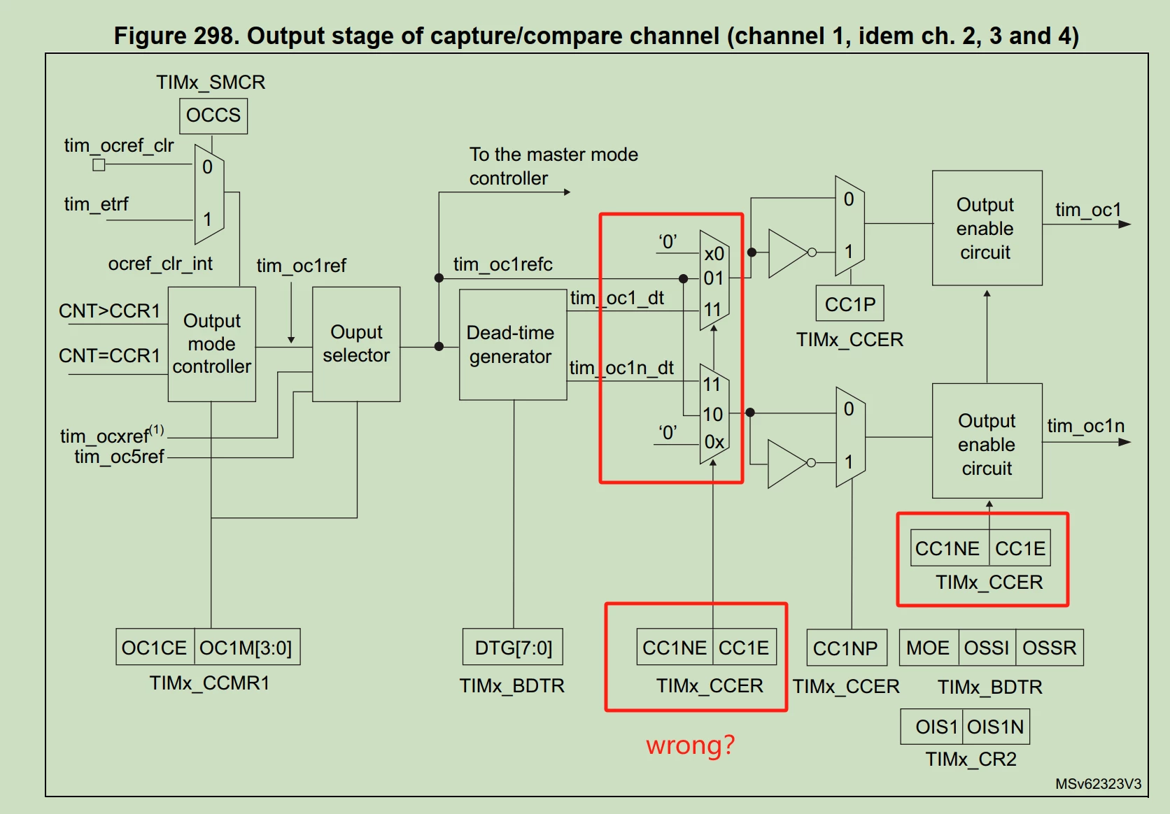
this figure is in rm0440-STM32G4 Series Reference manual. STM32F4, STM32F3 have the same TIM.

now I have some question:

1. how can I configure the Modules in the red box, such as selecting x0, 01 or 11?

2. I find CC1E and CC1NE can only enable the OC1 and OC1N output. WHY there are two function position(red box) for CC1E and CC1NE bit? is it something wrong?


Looking forward to hearing from the experts!

This topic has been closed for replies.
Best answer by waclawek.jan

CC1E and CC1NE are bits in TIMx_CCER, see description of that register in TIM chapter of RM.

The above picture illustrates the following facts:

  • Dead time is generated only if both these bits are set.
  • Also, if CCxNE is set (CH1N is enabled) and CCxE bit is cleared (CH1 is disabled), CH1N is not inverted.

JW

2 replies

waclawek.jan
waclawek.janBest answer
Super User
October 25, 2023

CC1E and CC1NE are bits in TIMx_CCER, see description of that register in TIM chapter of RM.

The above picture illustrates the following facts:

  • Dead time is generated only if both these bits are set.
  • Also, if CCxNE is set (CH1N is enabled) and CCxE bit is cleared (CH1 is disabled), CH1N is not inverted.

JW

Matt.Dash
Matt.DashAuthor
Associate II
October 25, 2023

thank you very much, this realy surprising!