DK.7
Associate III
January 17, 2024
Question

How to start PWM using the registers.

  • January 17, 2024
  • 13 replies
  • 6064 views

What am I doing wrong?

Why is PWM don't work on the STM32F767ZI?


RCC->APB2ENR |= 1; // Enable clock for TIM1 on APB2.
RCC->AHB1ENR |= RCC_AHB1ENR_GPIOEEN; // Enable clock for GPIOE port on AHB1.

GPIOE->MODER &= ~(1 << 18); // Clear/reset PE9 mode.
GPIOE->MODER |= (2 << 18); // Set PE9 mode.

// Enable alternative function AFIO. Connect TIM to the pin accordingly!
GPIOE->AFR[1] &= ~(0xF << 4); // Clear bits 4 to 7.
GPIOE->AFR[1] |= (1 << 4); // Set bit 9.

TIM1->PSC = 216 - 1; // Set prescaler for > 10KHz.
TIM1->ARR = 100 - 1; // Set auto-reload value for 1Hz.
TIM1->CCR1 = 50; // Set initial comparison value (PWM duty cycle).
TIM1->CNT = 0; // Reset the current count.

TIM1->CCMR1 |= (0x6UL << TIM_CCMR1_OC1M_Pos ); // Set PWM mode 1.
TIM1->CCMR1 |= (0x68 << 0);

TIM1->CCER = 1; // Enable PWM Channel 1.
TIM1->CR1 = 1; // Enable timer.
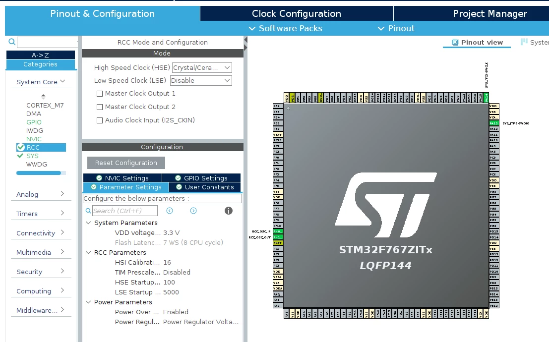
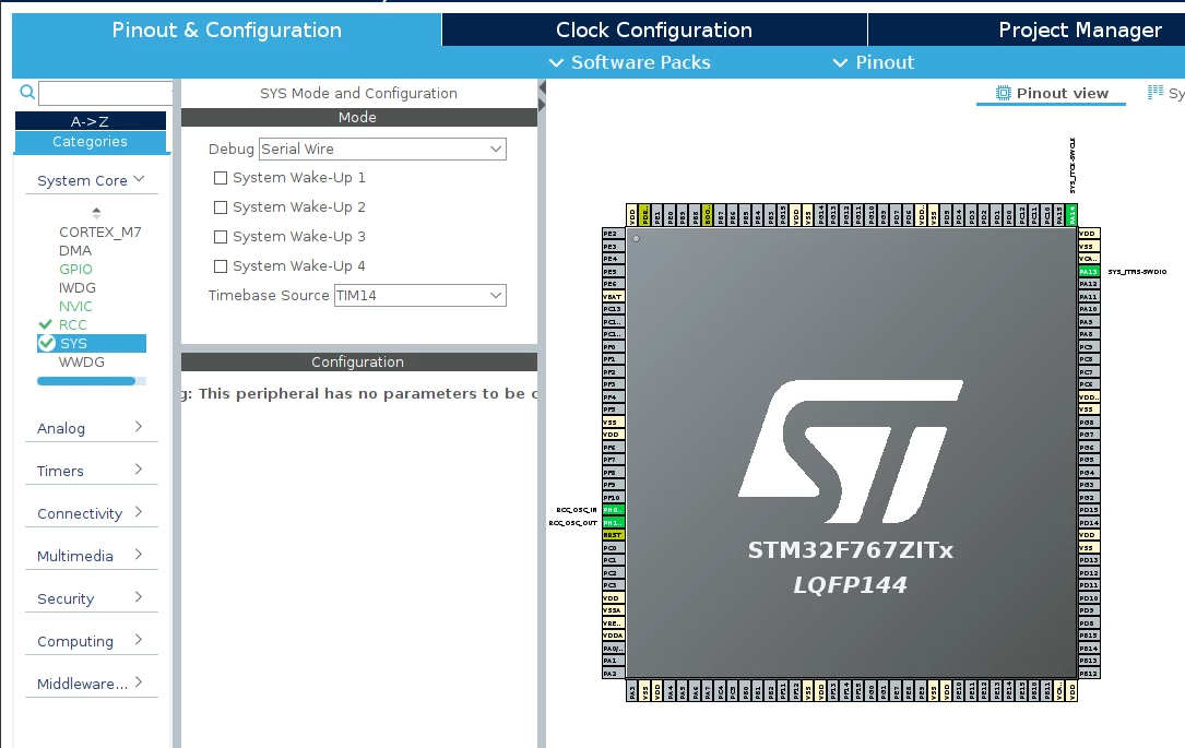


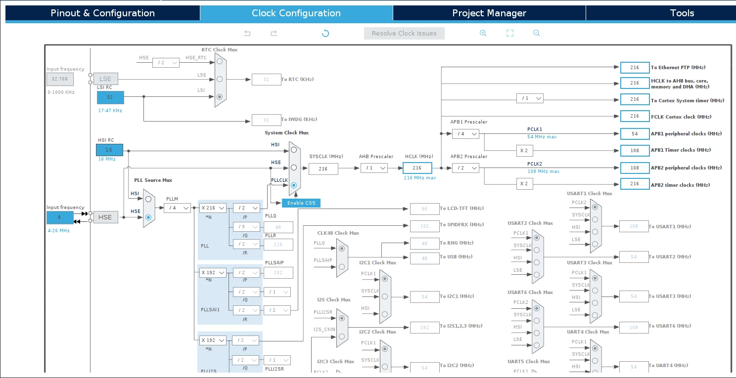
Q1.pngQ2.pngQ3.png

This topic has been closed for replies.

13 replies

TDK
January 17, 2024

On advanced timers, you need to set the MOE bit in the BDTR register to enable output.

"If you feel a post has answered your question, please click ""Accept as Solution""."
DK.7
DK.7Author
Associate III
January 17, 2024

Thank you for the response! I have set the necessary values in the register TIM1->BDTR->MOI.
But still, nothing is working!
The same settings work when using the HAL library! However, I'm not able to get it to work with the registers!

Q4.png

TDK
January 17, 2024

Not real sure. Is this a custom board or ST design? Might not be hooked up how you think. Recheck schematic.

Set up PE9 as a GPIO output and toggle it. to verify it connects to what you think it does.

You can also examine GPIOx->IDR register when PWM is active. For a 50% PWM, it should be toggling between 0 and 1 with equal probability.

What does "PWM don't work" mean here specifically? How are you verifying that it's active/inactive?

"If you feel a post has answered your question, please click ""Accept as Solution""."
DK.7
DK.7Author
Associate III
January 18, 2024

I checked it with a digital analyzer and an oscilloscope, see photo! The result is no signal with the same behavior on both devices.

I have a regular NUCLEO-F767ZI board that works perfectly if I create a project using the HAL library. However, when I try to implement a similar project using only registers, nothing works!1.png

AScha.3
Super User
January 18, 2024

So why dont you just use the working HAL , then look in debug , what the start_pwm_chxx  or whatever is doing - then you see, what you have to write to the TIM registers.

Or (as i did sometimes) just look in SFR view, what registers are set to some values, then set it to this values just by write to registers, without any HAL then. And you have it running...

If you feel a post has answered your question, please click on " Best Answer ".
LCE
Principal II
January 18, 2024

I have down this for a F767 Nucleo some years ago, I'm pretty sure it worked, just a little bit clock enable and GPIO HAL stuff:


/* TIM11 Initialization Function
 * 		PWM output for testing,
 *		GPIO PF7
 */

/* "manual" register settings, safer than Cube HAL stuff */
void MX_TIM11_Init(void)
{
	GPIO_InitTypeDef GPIO_InitStruct = { 0 };

	/* Peripheral clock enable */
	__HAL_RCC_TIM11_CLK_ENABLE();

	TIM11->CR1	= 0;
	TIM11->DIER 	= 0;
	TIM11->PSC	= 7;
	TIM11->ARR	= 29;			/* auto-reload: PWM frequency */
	TIM11->CCR1	= TIM11->ARR >> 1;	/* 50% duty cycle */
	TIM11->EGR	= 0;
	TIM11->CCMR1	= TIM_CCMR1_OC1M_2 | TIM_CCMR1_OC1M_1;
	TIM11->CCER	= TIM_CCER_CC1E | TIM_CCER_CC1P;
	TIM11->OR	= 0;

	TIM11->CNT 	= 0;
	TIM11->SR	= 0;

	/* Configure GPIO pin : Timer 11 channel output compare PWM PF7 */
	/* TIM11 GPIO Configuration PF7 ------> TIM11_CH1 */
	GPIO_InitStruct.Pin 		= GPIO_PIN_7;
	GPIO_InitStruct.Mode 		= GPIO_MODE_AF_PP;
	GPIO_InitStruct.Pull 		= GPIO_NOPULL;
	GPIO_InitStruct.Speed 		= GPIO_SPEED_FREQ_MEDIUM;//GPIO_SPEED_FREQ_HIGH;
	GPIO_InitStruct.Alternate 	= GPIO_AF3_TIM11;
	HAL_GPIO_Init(GPIOF, &GPIO_InitStruct);

	/* TIM11 enable */
	TIM11->CR1 = TIM_CR1_ARPE | TIM_CR1_CEN;
}


LCE
Principal II
January 18, 2024

When I compare my code to yours:

- TIM: you have not set the ARPE bit in CR1, not sure though if that is really needed, check RM

RM:

You must enable the corresponding preload register by setting the
OCxPE bit in the TIMx_CCMRx register, and eventually the auto-reload preload register (in
upcounting or center-aligned modes) by setting the ARPE bit in the TIMx_CR1 register.

IDK if that applies to your stuff.

- clock enables and GPIO:  that's where I am lazy and use the HAL stuff. Maybe just for checking, you use HAL stuff for that, then see if your PWM starts doing something.

DK.7
DK.7Author
Associate III
January 18, 2024

Thank you, I will verify everything and I'll reply to you!

MHank.1
Associate III
January 18, 2024

I wrote an article on ARM Timers using registers, NOT HAL, that might be of some help.


https://jaxcoder.com/Post/Index?guid=456f6a89-1a93-4a72-bab9-4cf3a9e7f9b6 


PartsBin - An Electronic Parts Organizer for Windows &#64; JaxCoder.com
waclawek.jan
Super User
January 18, 2024

Read out and check/post TIM and GPIO registers' content. That's always the first step in debugging software on mcu, as it works out of registers, not out of the source code.

JW