Lchal.1
Associate III
Feb 10, 2021 9:24 AM UTC
Solved

How to measure RMS voltage and Current coming from AC supply and calculate

Hi, i need to measure rms voltage and current choosing ADC channels in stm32f103.

i selected two channnels in ADC1 to read adc values . By using these channels i need to calculate rms voltage and current . But i am confused how to do it . is it necessary to do calibration also. can anyone help me how to write a code or how to start it please.

Thank you

This topic has been closed for replies.
Javier1
Javier1Best answer
Principal
Feb 10, 2021 11:58 AM UTC

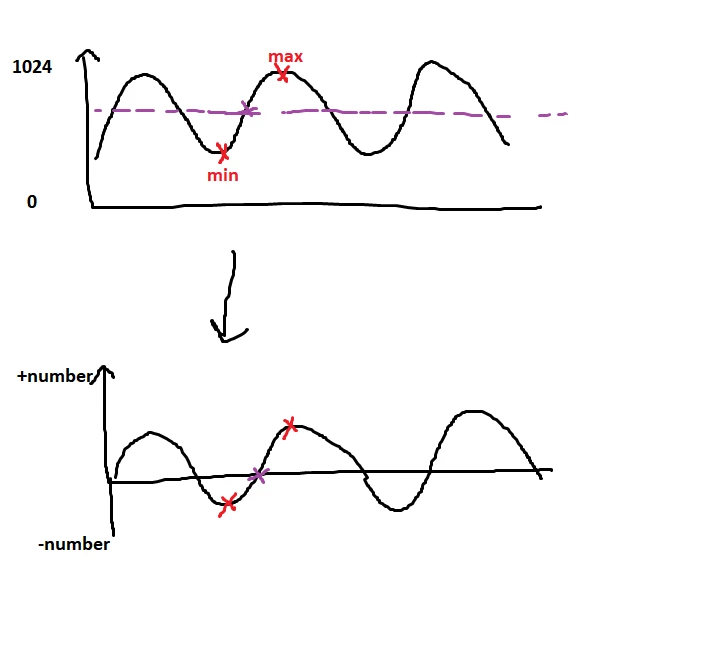
True RMS calculation:

1.Detect the 0 crossing (here is where the magic is)

2. offset your adc readings tothat 0

3. calculate the root square of every sample and average the results.

(the more samples you get the more precise your result is)0693W000007EhK5QAK.png 

Cheap-fix RMS calculation:

if your signal is going to have a very stable dc component (same average all the time) you can just make a peak detector and do Vrms=(1/sqrt2)*(Vmax-Vavg)

hit me up in https://www.linkedin.com/in/javiermuñoz/

4 replies

ST Technical Moderator
Feb 10, 2021 10:41 AM UTC

Hello @Lchal.1​ ,

The current can be measured through a resistor: by measuring the voltage across this resistor.

The RMS is an average, so it must average the values taken by the ADC by software.

Perhaps I did not understand your question.

So, I suggest adding more details and clarify your request to increase the chances of getting you an answer.

Imen

In order to give better visibility on the answered topics, please click on 'Best answer' on the reply which solved your issue or answered your question. Thanks
Lchal.1
Lchal.1Author
Associate III
Feb 10, 2021 11:53 AM UTC

 if(HAL _ADC _Start _DMA(&hadc1, (uint32_t*) adc Buffer, TOTAL_CHANNELS) != HAL_OK)

  return 0;

if(RMS _Sample_ Counter<RMS_TOTAL_SAMPLES) // it is given inside timer interrupt by setting 1kz

{

for(index1=0;index1<2;index1++)

{

temp_ ADC = adc Buffer[index1];

V1[index1] = V1[index1]+((float)temp _ADC*(float)temp _ADC);

V2[index1] = V2[index1]+(float)temp _ADC;

}

RMS _Sample _Counter++;

}

while(1)

{

 Delay_Count++;

 if(Delay_Count>=2500)

 {

  Delay_Count = 0;

  if(RMS_Sample_Counter>=RMS_TOTAL_SAMPLES) // i have set RMS_TOTAL_Samples as 1000

  {

  for(indx=0;indx<2;indx++)

  {

  //RMS_value[indx] = ((sqrtf((V1[indx]/100000.0)-((V2[indx]/100000.0)*(V2[indx]/100000.0))))/15.5);

  RMS_value[indx] = ((sqrtf((V1[indx]/1000.0)-((V2[indx]/1000.0)*(V2[indx]/1000.0))))/caliberate_factor);

  if(RMS_value[indx]>1.5)

  {

  Actual_Amps[indx] = RMS_value[indx];

  }

  else

  {

  Actual_Amps[indx] = 0.0;

  }

 /*

  for(indx=0;indx<3;indx++)

  {

  //Amps_Reading[indx] += 0.1;

  if(Amps_Reading[indx]>30)

  {

  Amps_Reading[indx] = 0;

  }

  Actual_Amps[indx] = Amps_Reading[indx];

  }

 */

  V1[indx] = 0;

  V2[indx] = 0;

  }

  RMS_Sample_Counter = 0;

  }

 }

}

this is the code i have done to calculate rms voltage and current can anyone help me if anything i need to add or is my code correct please

Thank you

Lchal.1
Lchal.1Author
Associate III
Feb 10, 2021 11:47 AM UTC

Thank you

Javier1
Javier1Best answer
Principal
Feb 10, 2021 11:58 AM UTC

True RMS calculation:

1.Detect the 0 crossing (here is where the magic is)

2. offset your adc readings tothat 0

3. calculate the root square of every sample and average the results.

(the more samples you get the more precise your result is)0693W000007EhK5QAK.png 

Cheap-fix RMS calculation:

if your signal is going to have a very stable dc component (same average all the time) you can just make a peak detector and do Vrms=(1/sqrt2)*(Vmax-Vavg)

hit me up in https://www.linkedin.com/in/javiermuñoz/