paul sauv
Associate III
February 28, 2018
Question

How to interpolate and compare 2 sine waves

  • February 28, 2018
  • 19 replies
  • 6005 views
Posted on February 28, 2018 at 22:23

Hi everyone,

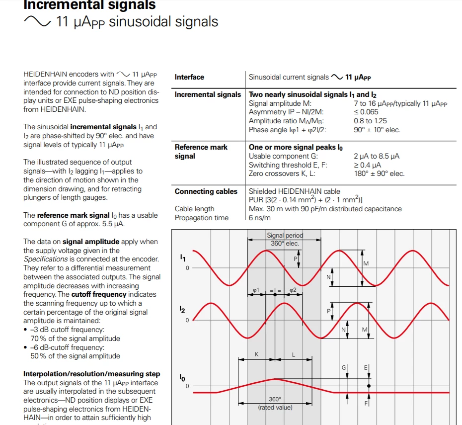
With my STM32F103C8T6 I would like to receive the 2 signals I1 and I2 from the picture below in order to convert to

https://community.st.com/tags#/?tags=square%20signal

.

All the square part is already coded and working great.

Now I would like to learn how to use this

https://community.st.com/tags#/?tags=sine%20waveform

and

#

signal and interpolate them such as the file attached in order to have a decent precision. For example, in my case the step of the wave is 20 microns so I would like to interpolate it by 20 in order to have 20 pulses of 1 micron.

This is an optical ruler on a milling machine so the ruler can travel in both ways with numerous direction changes

I'm a hobbyist so any bite of code is very welcomed

Right now, I only use Std periph lib, not HAL libraries.

Thank you for your help

0690X00000609qZQAQ.png

#square-signal #sine-waveform #cosine

Note: this post was migrated and contained many threaded conversations, some content may be missing.

    This topic has been closed for replies.

    19 replies

    henry.dick
    Associate II
    February 28, 2018
    Posted on February 28, 2018 at 23:00

    Easy, so long as you can express the 3rd signal as a result of the first two signals.

    If you cannot, we cannot either.

    valentin
    Associate III
    March 1, 2018
    Posted on March 01, 2018 at 01:19

    So for e.g. 6m/min feed rate you're looking at 100k pulses / sec, right? And you want to do the interpolation on a µC? I doubt that's possible.

    I'd look for a dedicated IC to do that. There are some around that spit out quadrature square signals which you can easily read on a mcu with your timers. -> no software overhead involved.

    paul sauv
    paul sauvAuthor
    Associate III
    March 1, 2018
    Posted on March 01, 2018 at 09:43

    100mm/sec is way above my feed rate but this is not the point as I'm building an hélicoïdal rotary divider, I won't send that much of pulse. But I would like to be able to interpolate the 2 sine /cosine wave then I will calculate the number of pulses to be sent

    But I have no idea how to proceed ? 

    valentin
    Associate III
    March 1, 2018
    Posted on March 01, 2018 at 19:31

    Hmm, you could hand-code the pulse thresholds into your code. would probably be the easiest way. Or you could model a generic sine-wave and put a kalman filter on top which then spits out the current phase angle phi which you can then use to generate the pulses.

    All of these methods seem too slow in my mind though but try anyway.

    Why don't you do some fooling around in matlab? Just create some sine/cosine data sets in there and then experiment with different approaches.

    Andrew Neil
    Super User
    March 1, 2018
    Posted on March 01, 2018 at 19:37

    Again, Resolver technology has been around for years - there must be plenty of prior art.

    Don't start by re-inventing the wheel ...

    A complex system that works is invariably found to have evolved from a simple system that worked.A complex system designed from scratch never works and cannot be patched up to make it work.
    Andrew Neil
    Super User
    March 1, 2018
    Posted on March 01, 2018 at 10:01

    That picture suggests that what you have is a Resolver:

    https://en.wikipedia.org/wiki/Resolver_(electrical)


    These are very long-established devices - so I suggest that you do some research & study into prior art; eg,

    https://www.google.co.uk/search?q=synchro+resolver


    As the Wikipedia article says,

    For the position evaluation,

    https://www.google.co.uk/search?q=Resolver-to-Digital+Converter

    are commonly used. They convert sine and cosine signal to binary signal (10 to 16 bit wide) that can more easily be used by the controller.
    A complex system that works is invariably found to have evolved from a simple system that worked.A complex system designed from scratch never works and cannot be patched up to make it work.
    paul sauv
    paul sauvAuthor
    Associate III
    March 3, 2018
    Posted on March 03, 2018 at 14:10

    Yes I am.

    I followed advices above and bought an specific IC: IC-NV

    henry.dick
    Associate II
    March 3, 2018
    Posted on March 03, 2018 at 15:29

    '

    I followed advices above and bought an specific IC: IC-NV'

    that's very unfortunate, as the article you linked to provided incredibly concise expression between the inputs and the outputs. it is quite easy to implement in a mcu.

    paul sauv
    paul sauvAuthor
    Associate III
    March 3, 2018
    Posted on March 03, 2018 at 15:31

    yes but I have absolutey no idea how to proceed as a beginner

    But I would be happy to understand if you explain piece of code

    AVI-crak
    Senior
    March 4, 2018
    Posted on March 04, 2018 at 12:12

    Industrial optical encoders give the data in a crude form, but without delays. With a slow movement - they manage to give the full result.

    The data from the optical encoder in its raw form is not a sound !!!, it can have a constant voltage in the static state.

    How to make a rapid rough conversion - to translate the analogue into a digital form, and submit to a free timer in encoder mode. You will have a momentary value for the position of the ruler.

    Separately monitor the rate of change in the readings of the ruler, as soon as the rate of change becomes sufficiently small - the result of the ADC measurement becomes relevant, and it can be used together with the encoder readings.