


Dat Tran
Senior II
January 7, 2025
Question

How to find DMA channel for Timer

  • January 7, 2025
  • 9 replies
  • 3296 views

We are working on STM32C071KBU6


In STM example TIM_DMA, I see it uses PA10 - TIM1_CH3 with DMA channel 5, but I could not find anything about this. Anyone know how to find this information? I would like to use different pins but don't know what DMA channel mapped to them.

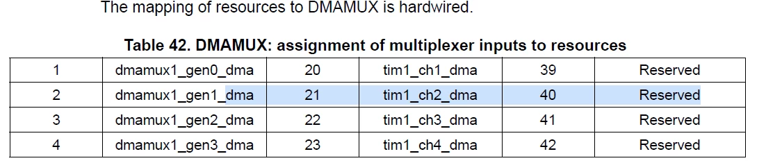
All I found is, in user manual, tim1_ch3_dma stick with 22, not sure what it means.
 

DatTran_0-1736288155168.png


This topic has been closed for replies.

9 replies

TDK
January 7, 2025

The STM32C0 doesn't have DMA channels the way than the STM32F7 does. Instead, the mapping is done through the DMAMUX. In this case, input 22 is TIM1 channel 3.

"If you feel a post has answered your question, please click ""Accept as Solution""."
Dat Tran
Dat TranAuthor
Senior II
January 8, 2025

Can you a bit more specific?

Here is a piece of my code and I already get it working on PA1 which is TIM1_CH2

I understand input 22 is TIM1 channel 3, 21 is TIM1_CH2, but my code, I don't need to know this number. All I need to know is channel to set to Instance, enable interrupt, example:

hdma_tim1_ch3.Instance = DMA1_Channel5;


I don't see how to use input "22" anywhere in ST example, how to use input "22"? what is relationship "input22" to DMA1_Channel5? 

__HAL_RCC_DMA1_CLK_ENABLE();
__HAL_RCC_TIM1_CLK_ENABLE();
__HAL_RCC_GPIOA_CLK_ENABLE();


HAL_NVIC_SetPriority(DMAMUX1_DMA1_CH4_5_IRQn, 0, 0);
HAL_NVIC_EnableIRQ(DMAMUX1_DMA1_CH4_5_IRQn);

Gpio_EnablePin(1, GPIO_MODE_AF_PP, GPIO_AF5_TIM1, GPIO_NOPULL, GPIO_SPEED_FREQ_VERY_HIGH);

htim_tim1_ch3.Instance = TIM1;
htim_tim1_ch3.Init.Period = 100;
htim_tim1_ch3.Init.Prescaler = 17;//(SystemCoreClock / 2500000) - 1; // 1us
htim_tim1_ch3.Init.ClockDivision = TIM_CLOCKDIVISION_DIV1;
htim_tim1_ch3.Init.CounterMode = TIM_COUNTERMODE_UP;

__HAL_RCC_TIM1_FORCE_RESET();
__HAL_RCC_TIM1_RELEASE_RESET();


if (HAL_TIM_OC_Init(&htim_tim1_ch3) != HAL_OK)
{
return ;
}

TIM_OC_InitTypeDef sConfig = { 0 };

sConfig.OCMode = TIM_OCMODE_TOGGLE;
sConfig.OCPolarity = TIM_OCPOLARITY_LOW;//TIM_OCPOLARITY_HIGH;// : TIM_OCPOLARITY_LOW;

sConfig.Pulse = time_data[0];

if (HAL_TIM_OC_ConfigChannel(&htim_tim1_ch3, &sConfig, TIM_CHANNEL_2) != HAL_OK)
{
return ;
}

hdma_tim1_ch3.Init.Direction = DMA_MEMORY_TO_PERIPH;
hdma_tim1_ch3.Init.PeriphInc = DMA_PINC_DISABLE;
hdma_tim1_ch3.Init.MemInc = DMA_MINC_ENABLE;
hdma_tim1_ch3.Init.PeriphDataAlignment = DMA_PDATAALIGN_WORD;
hdma_tim1_ch3.Init.MemDataAlignment = DMA_MDATAALIGN_WORD;
hdma_tim1_ch3.Init.Mode = 0;
hdma_tim1_ch3.Init.Priority = DMA_PRIORITY_LOW;

hdma_tim1_ch3.Init.Request = LL_DMAMUX_REQ_TIM1_CH2;
hdma_tim1_ch3.Instance = DMA1_Channel5;

if (HAL_DMA_Init(&hdma_tim1_ch3) != HAL_OK) {
return;
}

__HAL_LINKDMA(&htim_tim1_ch3,hdma[TIM_DMA_ID_CC2], hdma_tim1_ch3);

htim_tim1_ch3.Instance->CNT = 0;

__HAL_TIM_ENABLE_IT(&htim_tim1_ch3, TIM_IT_UPDATE);

if (HAL_TIM_OC_Start_DMA(&htim_tim1_ch3, TIM_CHANNEL_2, &time_data[1], sizeof(time_data)/4 - 1) != HAL_OK) {
return;
}


mƎALLEm
ST Technical Moderator
January 8, 2025

Hello @Dat Tran ,

Please use </> button to share your code. refer to this link. I'm editing your post.

Thank you.

To give better visibility on the answered topics, please click "Best answer" on the reply which solved your issue or answered your question.
gbm
Super User
January 13, 2025

That's arbitrary - up to you. Any channel may be used for any peripheral.

My STM32 stuff on github - compact USB device stack and more: https://github.com/gbm-ii/gbmUSBdevice