

Associate III
Apr 12, 2024 5:42 PM UTC
Question

How to connect a STM32F4xxxRE on a custom PCB

Hello,

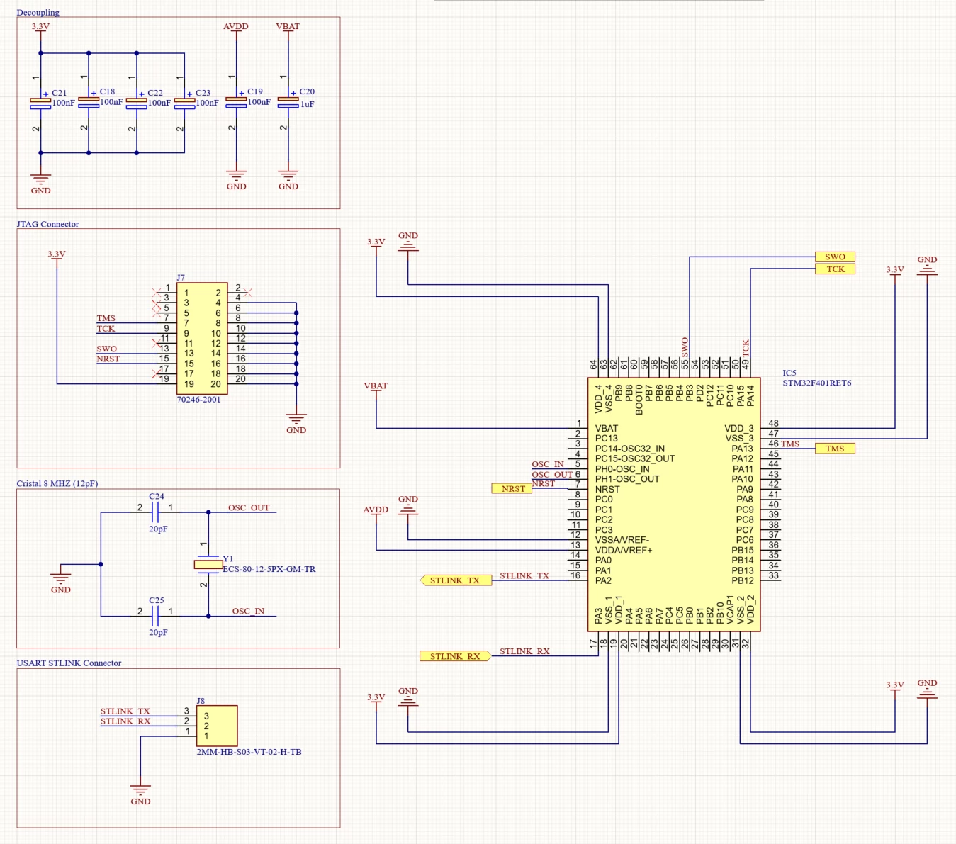
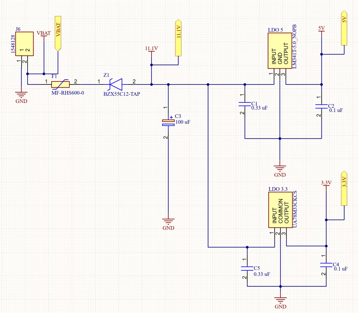
This is the first time I've designed a PCB with a stm32. I found a PDF on the internet that gives me an example of a Nucleo connection but I'm not sure if my schematic is correct.
I don't need all the headerts or the usb connection (I'll be using Stlink v2).
Here's a screenshot of my MCU schematic and my power supply schematic.
Paulo971_0-1712943662324.pngPaulo971_1-1712943686124.png


Can anyone tell me if this is correct or if I need to add or remove components and where?


Best regard.

Paulo971

This topic has been closed for replies.

10 replies

Michal Dudka
Lead
Apr 12, 2024 5:54 PM UTC

Add capacitor at VCAP1 (AFAIK 2u2, but consult with datasheet).
Bring required level to boot pin.
Connect power supply to AVDD.
Do not connect 11.1V to VBAT pin on MCU !

Tesla DeLorean
Guru
Apr 12, 2024 5:59 PM UTC

Single VCAP pin, typically 4u7 F, two pins 2u2 F on each

Pull Down in BOOT0 to ensure your code in FLASH starts, perhaps option to go HIGH if you need to start the ROM based System Loader

Tips, Buy me a coffee, or three.. PayPal Venmo (See Profile) Up vote any posts that you find helpful, it shows what's working..
Paulo971Author
Associate III
Apr 12, 2024 8:37 PM UTC

Thank you very much, i'll fixe that ASAP.

As far as the stlink connection is concerned, everything's fine?

Chris21
Associate II
Apr 12, 2024 9:21 PM UTC

Chris21_0-1712956697185.png

May want to connect VAPP, it's the MCU generated VDD to tell the ST-Link what signal level to use for the programming pins. 

.