

NOMal.1
Associate
May 16, 2023
Solved

How does the Timer - DMA - Look up table to DAC index get set? Is it possible to change the index

I have a project where I'm using a Nucloe G474RE to produce a sine wave, all is working great; I have an array of 2500 values which produce a SINE wave starting at 0 degrees; I would like to add 2 further Sine waves starting 120 and 240 degrees later.

To do this, I could create 2 additional arrays with the values shifted to reflect the 120-degree and 240 degrees shift, but I was wondering whether I could use one array and produce the remaining 2 arrays by preloading the index the timer produces for phase 2 and 3 , indexing, reading and sending the value to the 2nd and 3rd DAC output.

Is this achievable

Thanks for any guidance

Nick

I think I know how this could work, but I have to set the registers manually rather than using the HAL,

The HAL seems to hide the details on how to set the source address,

DMA1_Channel1->CPAR = (unint32_t(&dataArray[index_to_start_from); //DMA in circular mode.

Can I override this in the Cubemx generated project, or do I need to code without using CubeMX

Thanks

Nick
This topic has been closed for replies.
NOMal.1
NOMal.1Best answer
Associate
May 19, 2023

Thanks Michal,

I have managed to sort it using DMA only , no software in main() at all.

Its really simple .

I have a 1 x array with 5000 values as the look up table covering 2 cycles (Thanks KnarfB)

When you Start each DAC you add the number you want to index from in the HAL_DAC_Start_DMA call

HAL_DAC_Start_DMA(&hdac1, DAC_CHANNEL_1, (uint32_t*)Wave_LUT_BIG

HAL_DAC_Start_DMA(&hdac1, DAC_CHANNEL_2, (uint32_t*)(Wave_LUT_BIG+1666

HAL_DAC_Start_DMA(&hdac2, DAC_CHANNEL_1, (uint32_t*)(Wave_LUT_BIG+1070

the only inconsistency Is that DAC 1 channels 1 and 2 are synchronised but DAC 2 channel 1 is delayed compared the DAC 1 channels , hence why the index is lower on the 3rd DAC output.

Regards

Nick

Code snippet below.

 MX_DMA_Init();

 MX_DAC1_Init();

 MX_TIM2_Init();

 MX_DAC2_Init();

 MX_USART2_UART_Init();

 /* USER CODE BEGIN 2 */

 HAL_DAC_Start_DMA(&hdac1, DAC_CHANNEL_1, (uint32_t*)Wave_LUT_BIG, 2500, DAC_ALIGN_12B_R);     //Phase A Start At 0 degrees

 HAL_TIM_Base_Start(&htim2);

 HAL_DAC_Start_DMA(&hdac1, DAC_CHANNEL_2, (uint32_t*)(Wave_LUT_BIG+1666), 2500, DAC_ALIGN_12B_R);  //Phase B Start At 120 degrees +1666

 HAL_TIM_Base_Start(&htim2);

 HAL_DAC_Start_DMA(&hdac2, DAC_CHANNEL_1, (uint32_t*)(Wave_LUT_BIG+1070), 2500, DAC_ALIGN_12B_R);  //Phase C Start At 240 degrees

 HAL_TIM_Base_Start(&htim2);


_legacyfs_online_stmicro_images_0693W00000bkT05QAE.png

8 replies

KnarfB
Super User
May 17, 2023

Multiple DMAs on the same array will work, unless at very high frequencies when bus access may become a bottleneck. Keep in mind that you need a longer array (say 2 periods) if you start not at the beginning. You may add your code in USER code sections in a generated HAL project.

Why do you need overriding the HAL code? Didn't code like

 HAL_DAC_Start_DMA(&hdac1, DAC_CHANNEL_1, (uint32_t*)buffer, DAC_BUFFER_SAMPLES, DAC_ALIGN_12B_R);
 HAL_DAC_Start_DMA(&hdac1, DAC_CHANNEL_2, (uint32_t*)(buffer+256), DAC_BUFFER_SAMPLES, DAC_ALIGN_12B_R);

work?

hth

KnarfB

NOMal.1
NOMal.1Author
Associate
May 17, 2023

Thanks KnarfB,

The array is only holding values for one cycle and the max frequency is 60 Hz , thanks for the code snippet , it looks really simple to index into the array.

if it's in circular mode, won't it loop around, or maybe it will try and continue to increment to the end of the 2500 array size and then loop around to 0?

Regards

Nick

NOMal.1
NOMal.1Author
Associate
May 18, 2023

You, of course, were correct; I needed 2 cycles of data in the array.

I had to add an additional Dac channel for the 3rd phase output. I don't know the latency between the 2 DACs, but they are not in synchronisation unless I'm missing something,

phase 1 and 2 on DAC1 channels 1 and 2 are synchronised,

but phase 3 on DAC2 channel 1 isn't synchronised with DAC1. it's not a problem because I need to offset each channel anyway.

Thanks for your help

Michal Dudka
Lead
May 19, 2023

If i understand correctly, you need to generate three same (sine) waveforms. Using three memory buffers is an obvious waste of memory. you simply want to have only one buffer and just to start DMA in circular mode, but with shifted index. DMA generally does not allow this, but you can do simple trick.

  1. Set up all three DACs with disabled output
  2. Set up all three DMA channels to (only one) buffer
  3. Enable software triggered mode for one (second) DAC channel
  4. Generate by software number of DAC triggers - that shifts corresponding DMA to desired phase shift
  5. Do the same for third channel (to shift third channel)
  6. Enable all DACs outputs
  7. Switch all DAC for trigger you are using in regular operation
  8. Run... from now you should seen phase shifted outputs, running from single buffer

NOMal.1
NOMal.1AuthorBest answer
Associate
May 19, 2023

Thanks Michal,

I have managed to sort it using DMA only , no software in main() at all.

Its really simple .

I have a 1 x array with 5000 values as the look up table covering 2 cycles (Thanks KnarfB)

When you Start each DAC you add the number you want to index from in the HAL_DAC_Start_DMA call

HAL_DAC_Start_DMA(&hdac1, DAC_CHANNEL_1, (uint32_t*)Wave_LUT_BIG

HAL_DAC_Start_DMA(&hdac1, DAC_CHANNEL_2, (uint32_t*)(Wave_LUT_BIG+1666

HAL_DAC_Start_DMA(&hdac2, DAC_CHANNEL_1, (uint32_t*)(Wave_LUT_BIG+1070

the only inconsistency Is that DAC 1 channels 1 and 2 are synchronised but DAC 2 channel 1 is delayed compared the DAC 1 channels , hence why the index is lower on the 3rd DAC output.

Regards

Nick

Code snippet below.

 MX_DMA_Init();

 MX_DAC1_Init();

 MX_TIM2_Init();

 MX_DAC2_Init();

 MX_USART2_UART_Init();

 /* USER CODE BEGIN 2 */

 HAL_DAC_Start_DMA(&hdac1, DAC_CHANNEL_1, (uint32_t*)Wave_LUT_BIG, 2500, DAC_ALIGN_12B_R);     //Phase A Start At 0 degrees

 HAL_TIM_Base_Start(&htim2);

 HAL_DAC_Start_DMA(&hdac1, DAC_CHANNEL_2, (uint32_t*)(Wave_LUT_BIG+1666), 2500, DAC_ALIGN_12B_R);  //Phase B Start At 120 degrees +1666

 HAL_TIM_Base_Start(&htim2);

 HAL_DAC_Start_DMA(&hdac2, DAC_CHANNEL_1, (uint32_t*)(Wave_LUT_BIG+1070), 2500, DAC_ALIGN_12B_R);  //Phase C Start At 240 degrees

 HAL_TIM_Base_Start(&htim2);


_legacyfs_online_stmicro_images_0693W00000bkT05QAE.png

Michal Dudka
Lead
May 19, 2023

OK, that is nice. All DAC can be perfectly synchronised if are configured in trigger mode. One timer triggers DAC conversion on all three channels simultaneously. (Start timer only once, after "starting" all three DMA channels)

NOMal.1
NOMal.1Author
Associate
June 24, 2023

Hi All, 

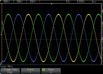
I have a further query about the DAC output for this that is puzzling me,  I have 3 sine waves all DAC conversions triggered correctly  but I seem to have lost the bottom portion of the sine 1 and 2 ( these are on the same DAC) ,  it was working fine until I connected the output of this on pin PA5 and PA6 to the input of an OPAMPS,  I think I have somehow damaged the buffer that I'm using inside the STM32 and it no longer outputs the full swing in voltage.

Here's a screen grab of the scope for the 3 phases.  Has anyone seen this before?  and is it possible to calibrate the output to correct it?


Thanks 

Nick

NOMal1_1-1687621107656.png
