ForgottenTale
Associate
May 27, 2022
Question

How change the PWM polarity of CH2N during runtime ?

  • May 27, 2022
  • 9 replies
  • 6022 views

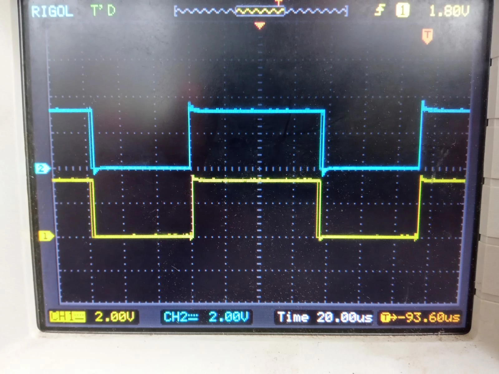
I have set Timer 8 to PWM Generation CH2 CH2N. Based on the value read by the ADC, I want to change the polarity of both CH2 and CH2N. I have found that using

__HAL_TIM_SET_CAPTUREPOLARITY

, I could change the polarity of CH20693W00000NqkcWQAR.jpg but the polarity of CH1N remains the same as shown in the image. So how could I change the polarity of both CH2 CH2N ?

This topic has been closed for replies.

9 replies

KnarfB
Super User
May 27, 2022

__HAL_TIM_SET_CAPTUREPOLARITY is for input capture, but not for output compare which does the PWM output here. You may switch from PWM mode 1 to PWM mode 2.

hth

KnarfB

ForgottenTale
Associate
May 27, 2022

Which HAL function will do that during runtime ?

waclawek.jan
Super User
May 27, 2022

> __HAL_TIM_SET_CAPTUREPOLARITY is for input capture, but not for output compare which does the PWM output here.

It's the same bit, TIMx_CCER.CCxP, even if maybe Cube/HAL has different incantations for it.

The CCxN channel's polarity is similarly controlled by TIMx_CCER.CCxNP. You can try to find some Cube/HAL macro for that if you want, Cube is open source.

Output Compare mode is determined by TIMx_CCMRx.OCxM field, simply change that field for different mode.

Read the TIM chapter in RM.

JW

ForgottenTale
Associate
May 29, 2022

How do I write the code for it? I am new to programming this type of board. I have only experience in programming Arduino

waclawek.jan
Super User
May 29, 2022

TIM8->CCER |= TIM_CCER_CC2NE [EDIT] see post below [/EDIT]

I started to write you a longer answer, but then it turned into this.

JW

ForgottenTale
Associate
May 29, 2022

This doesn't seem to work. The PWM isn't getting inverted

waclawek.jan
Super User
May 29, 2022

Ufff.... sorry.... CCxNE is the Enable bit for the TIMx_CHxN channel. Polarity is swapped using the CCxNP bit:

TIM8->CCER |= TIM_CCER_CC2NP;

JW

ForgottenTale
Associate
May 29, 2022

PWM channel of CH2N got inverted, but it didn't work for CH2. Also, I need toggle between non-inverted and inverted PWM based on the value read from the ADC. How can i do that ?

I don't know if the code given below is the correct way to toggle between PWM mode. But it is definitely working.

 void HAL_ADC_ConvCpltCallback(ADC_HandleTypeDef* hadc)
{
 value = HAL_ADC_GetValue(&hadc1);
 voltage = ReadDCVoltage25(value);
 
	if(voltage>50){
	__HAL_TIM_SET_CAPTUREPOLARITY(&htim1,TIM_CHANNEL_2,TIM_INPUTCHANNELPOLARITY_FALLING);
	TIM1->CCER |= TIM_CCER_CC2NP ;
		
	}
	else if(voltage<50){
	__HAL_TIM_SET_CAPTUREPOLARITY(&htim1,TIM_CHANNEL_2,TIM_INPUTCHANNELPOLARITY_RISING);
	}
}

waclawek.jan
Super User
May 29, 2022

> PWM channel of CH2N got inverted, but it didn't work for CH2.

As I said like 3 posts ago, it's CCxP for the TIMx_CHx and CCxNP for TIMx_CHxN.

TIM8->CCER |= TIM_CCER_CC2P;

Have you read the TIM chapter in RM? And within it, the CCER register description?

Have you experimented with the TIM registers in the debugger?

JW