

How can UART_Tx impact neighboring GPIO pins?
I have a STM32G071 where, among other stuff, an UART interface an a GPIO input are configured.
UART is mapped to PA9 - PA12 (Tx, Rx, CTS, RTS).
PA8 is configured as GPIO input mode (no pull-up, pull-down). On the net connected to PA8 is a hall sensor with open-drain output. This net has an external 10k pull-up resistor.
GPIO ports are initialized first, then UART.
When I stop the code after GPIO init, the hall sensor input works like a charm. The signal is 3 V when no magnetic field is present, and 0 V when the field is present. The GPIO input register show the correct value.
The moment I initialize UART, more specific, when the "transmitter enable" bit USART_CR1->TE the voltage at PA8 drops from 3 V to 1 V. When UART communication is started, the UART_Tx message is visible on the net of PA8. The blue signal is PA8 and the red signal is UART_Tx.
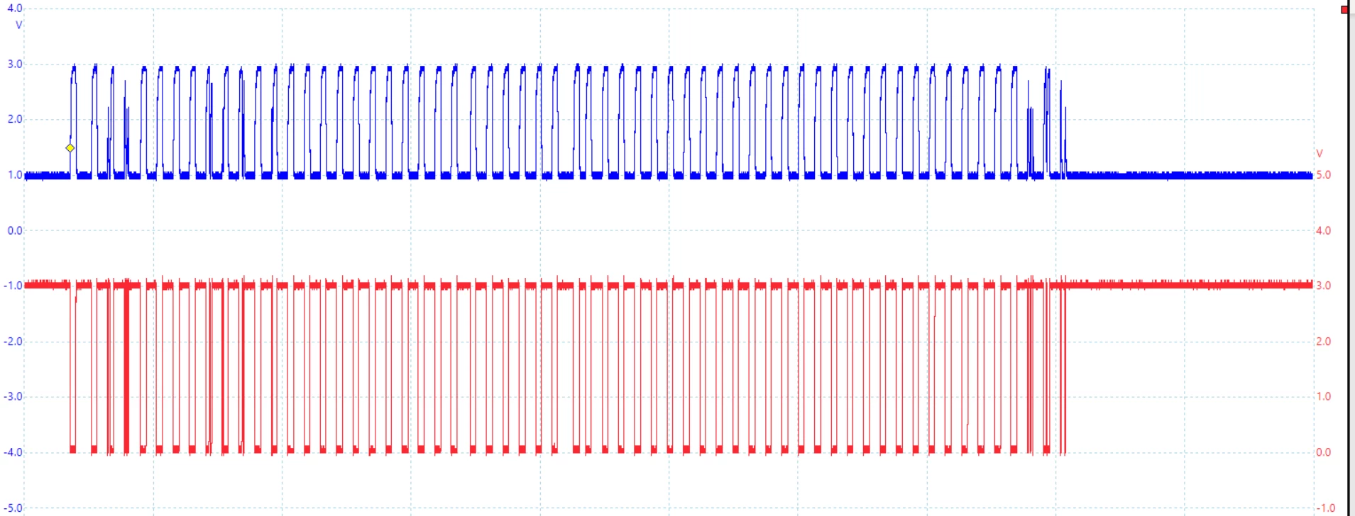
The GPIO configuration of PA8 does not change while UART is configured. It still works as input. When I connect the net directly to 3 V, it shows a '1' in the GPIO input register.
Since PA8 goes to 1 V when UART_Tx is high, it is not a resistive coupling from the PCB (then the signals would be in phase).
Apart from the close proximity of the pins, UART_Tx is PA9, there is no connection between those pins. The two nets are only close to each other at the MCU.
The effect showed up on all three PCBs I looked at.
When I measure the resistance between PA8 and PA9 the multi-meter shows approx. 330 kOhms.
Can anybody help? Did anybody see this sort of behavior before?

