WBach
Associate II
July 29, 2020
Question

HAL_ERROR calling HAL_TIM_PWM_Start_DMA to generate variable duty cycle PWM

  • July 29, 2020
  • 18 replies
  • 13911 views

Hello,

i am trying to generate a fixed 800kHz PWM signal with variable duty cycle on a STM32F446RE (Nucleo-446RE). As you already might have suspected, i am intending to drive WS2812B LEDs.

For this I intend to let TIM1 run at 800kHz and have TIM_CH1 running in PWM-Mode1 outputting to CH1-Pin. Doing just this works, I get a appropriate PWM signals. But now I also have to change the duty cycle every cycle/bit.

I intend to do this with DMA. A Memory to Peripheral Request putting values from a buffer in memory into the OCR1 Register of TIM1 should alter the duty cycle. This request should be triggered by TIM1 overflowing; TIM1_UP should trigger the request.

However, testing this basic concept fails and I tried to get this working for a long time now.

To realise this concept (which is valid or isn't it?) I used the STM32CubeIDE with STM32CubeMX.

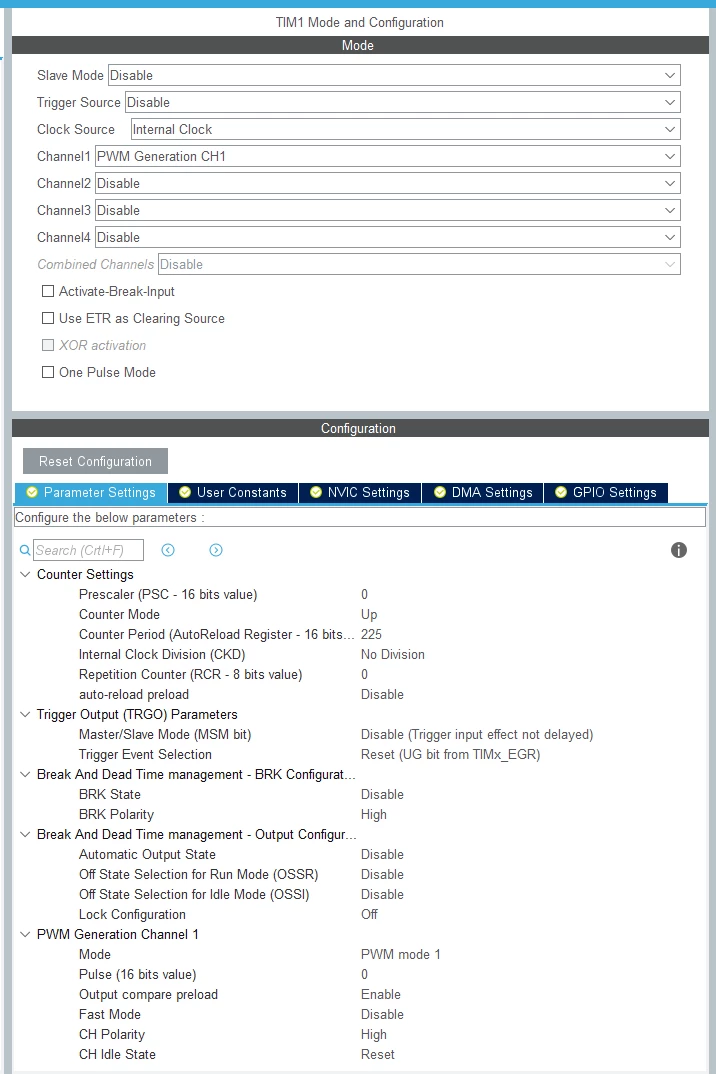
In CubeMX I configured TIM1 to be clocked at around 800kHz by setting no prescaler, a Counter Period of 225, setting Channel1 to PWM_Generation_CH1 with PWM_Mode_1.

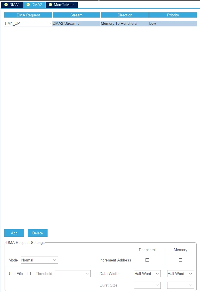
For DMA I added a request triggered by TIM1_UP from Memory to Peripheral with a data width of half_word.

The CubeMX settings are also visible in the pictures of it:
0693W000003BfWlQAK.png

0693W000003BfVaQAK.png

To now enable DMA actually putting values from a buffer in the CCR1 register to alter the duty cycle, I looked at the HAL Documentation and tried using the function:

HAL_StatusTypeDef HAL_TIM_PWM_Start_DMA (TIM_HandleTypeDef * htim, uint32_t Channel, uint32_t * pData, uint16_t Length)

, since its description "Starts the TIM PWM signal generation in DMA mode." and its arguments seem to be just what I'm looking for.

However, when actually executing it by calling

HAL_TIM_PWM_Start_DMA(&htim1, TIM_CHANNEL_1, data, 1);

it returns HAL_ERROR and well, the CCR1 value doesn't get updated.

I tried to troubleshoot it but kind of reached an impass.

I traced the origin of the return value HAL_ERROR:

HAL_TIM_PWM_Start_DMA is calling HAL_DMA_Start_IT.

If HAL_DMA_Start_IT doesn't return HAL_OK, HAL_TIM_PWM_Start_DMA returns HAL_ERROR.

In my case, HAL_DMA_Start_IT returns HAL_BUSY. This is due to its hdma->State not being HAL_DMA_STATE_READY.

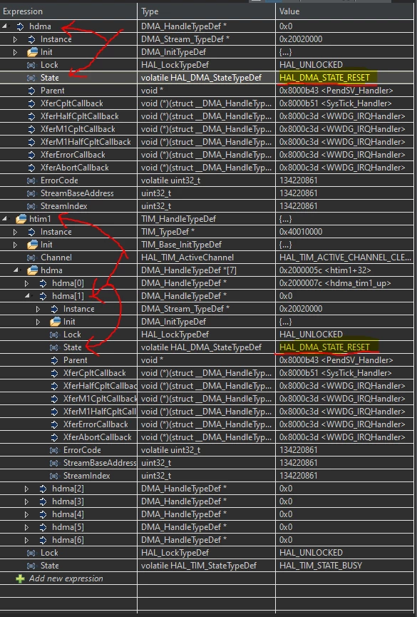
I checked and instead of that, hdma->State is HAL_DMA_STATE_RESET.

So, htim1.hdma[1].State is HAL_DMA_STATE_RESET, when calling HAL_TIM_PWM_Start_DMA; In HAL_TIM_PWM_Start_DMA htim1.hdma[1] is passed to HAL_DMA_Start_IT as the argument hdma.

The described tracing above is also visible through the source of these functions and the attached image of the debugged TypeDef values:

HAL_StatusTypeDef HAL_TIM_PWM_Start_DMA(TIM_HandleTypeDef *htim, uint32_t Channel, uint32_t *pData, uint16_t Length)
{
 uint32_t tmpsmcr;
 
 /* Check the parameters */
 assert_param(IS_TIM_CCX_INSTANCE(htim->Instance, Channel));
 
 if (htim->State == HAL_TIM_STATE_BUSY)
 {
 return HAL_BUSY;
 }
 else if (htim->State == HAL_TIM_STATE_READY)
 {
 if ((pData == NULL) && (Length > 0U))
 {
 return HAL_ERROR;
 }
 else
 {
 htim->State = HAL_TIM_STATE_BUSY;
 }
 }
 else
 {
 /* nothing to do */
 }
 
 switch (Channel)
 {
 case TIM_CHANNEL_1:
 {
 /* Set the DMA compare callbacks */
 htim->hdma[TIM_DMA_ID_CC1]->XferCpltCallback = TIM_DMADelayPulseCplt;
 htim->hdma[TIM_DMA_ID_CC1]->XferHalfCpltCallback = TIM_DMADelayPulseHalfCplt;
 
 /* Set the DMA error callback */
 htim->hdma[TIM_DMA_ID_CC1]->XferErrorCallback = TIM_DMAError ;
 
 /* Enable the DMA stream */
 if (HAL_DMA_Start_IT(htim->hdma[TIM_DMA_ID_CC1], (uint32_t)pData, (uint32_t)&htim->Instance->CCR1, Length) != HAL_OK)
 {
 return HAL_ERROR;
 }
 
 /* Enable the TIM Capture/Compare 1 DMA request */
 __HAL_TIM_ENABLE_DMA(htim, TIM_DMA_CC1);
 break;
 }
 
 case TIM_CHANNEL_2:
 {
 /* Set the DMA compare callbacks */
 htim->hdma[TIM_DMA_ID_CC2]->XferCpltCallback = TIM_DMADelayPulseCplt;
 htim->hdma[TIM_DMA_ID_CC2]->XferHalfCpltCallback = TIM_DMADelayPulseHalfCplt;
 
 /* Set the DMA error callback */
 htim->hdma[TIM_DMA_ID_CC2]->XferErrorCallback = TIM_DMAError ;
 
 /* Enable the DMA stream */
 if (HAL_DMA_Start_IT(htim->hdma[TIM_DMA_ID_CC2], (uint32_t)pData, (uint32_t)&htim->Instance->CCR2, Length) != HAL_OK)
 {
 return HAL_ERROR;
 }
 /* Enable the TIM Capture/Compare 2 DMA request */
 __HAL_TIM_ENABLE_DMA(htim, TIM_DMA_CC2);
 break;
 }
 
 case TIM_CHANNEL_3:
 {
 /* Set the DMA compare callbacks */
 htim->hdma[TIM_DMA_ID_CC3]->XferCpltCallback = TIM_DMADelayPulseCplt;
 htim->hdma[TIM_DMA_ID_CC3]->XferHalfCpltCallback = TIM_DMADelayPulseHalfCplt;
 
 /* Set the DMA error callback */
 htim->hdma[TIM_DMA_ID_CC3]->XferErrorCallback = TIM_DMAError ;
 
 /* Enable the DMA stream */
 if (HAL_DMA_Start_IT(htim->hdma[TIM_DMA_ID_CC3], (uint32_t)pData, (uint32_t)&htim->Instance->CCR3, Length) != HAL_OK)
 {
 return HAL_ERROR;
 }
 /* Enable the TIM Output Capture/Compare 3 request */
 __HAL_TIM_ENABLE_DMA(htim, TIM_DMA_CC3);
 break;
 }
 
 case TIM_CHANNEL_4:
 {
 /* Set the DMA compare callbacks */
 htim->hdma[TIM_DMA_ID_CC4]->XferCpltCallback = TIM_DMADelayPulseCplt;
 htim->hdma[TIM_DMA_ID_CC4]->XferHalfCpltCallback = TIM_DMADelayPulseHalfCplt;
 
 /* Set the DMA error callback */
 htim->hdma[TIM_DMA_ID_CC4]->XferErrorCallback = TIM_DMAError ;
 
 /* Enable the DMA stream */
 if (HAL_DMA_Start_IT(htim->hdma[TIM_DMA_ID_CC4], (uint32_t)pData, (uint32_t)&htim->Instance->CCR4, Length) != HAL_OK)
 {
 return HAL_ERROR;
 }
 /* Enable the TIM Capture/Compare 4 DMA request */
 __HAL_TIM_ENABLE_DMA(htim, TIM_DMA_CC4);
 break;
 }
 
 default:
 break;
 }
 
 /* Enable the Capture compare channel */
 TIM_CCxChannelCmd(htim->Instance, Channel, TIM_CCx_ENABLE);
 
 if (IS_TIM_BREAK_INSTANCE(htim->Instance) != RESET)
 {
 /* Enable the main output */
 __HAL_TIM_MOE_ENABLE(htim);
 }
 
 /* Enable the Peripheral, except in trigger mode where enable is automatically done with trigger */
 tmpsmcr = htim->Instance->SMCR & TIM_SMCR_SMS;
 if (!IS_TIM_SLAVEMODE_TRIGGER_ENABLED(tmpsmcr))
 {
 __HAL_TIM_ENABLE(htim);
 }
 
 /* Return function status */
 return HAL_OK;
}
HAL_StatusTypeDef HAL_DMA_Start_IT(DMA_HandleTypeDef *hdma, uint32_t SrcAddress, uint32_t DstAddress, uint32_t DataLength)
{
 HAL_StatusTypeDef status = HAL_OK;
 
 /* calculate DMA base and stream number */
 DMA_Base_Registers *regs = (DMA_Base_Registers *)hdma->StreamBaseAddress;
 
 /* Check the parameters */
 assert_param(IS_DMA_BUFFER_SIZE(DataLength));
 
 /* Process locked */
 __HAL_LOCK(hdma);
 
 if(HAL_DMA_STATE_READY == hdma->State)
 {
 /* Change DMA peripheral state */
 hdma->State = HAL_DMA_STATE_BUSY;
 
 /* Initialize the error code */
 hdma->ErrorCode = HAL_DMA_ERROR_NONE;
 
 /* Configure the source, destination address and the data length */
 DMA_SetConfig(hdma, SrcAddress, DstAddress, DataLength);
 
 /* Clear all interrupt flags at correct offset within the register */
 regs->IFCR = 0x3FU << hdma->StreamIndex;
 
 /* Enable Common interrupts*/
 hdma->Instance->CR |= DMA_IT_TC | DMA_IT_TE | DMA_IT_DME;
 
 if(hdma->XferHalfCpltCallback != NULL)
 {
 hdma->Instance->CR |= DMA_IT_HT;
 }
 
 /* Enable the Peripheral */
 __HAL_DMA_ENABLE(hdma);
 }
 else
 {
 /* Process unlocked */
 __HAL_UNLOCK(hdma);	 
 
 /* Return error status */
 status = HAL_BUSY;
 }
 
 return status;
}
0693W000003BfWgQAK.png

I tried to figure out, why htim1.hdma[1].State is stuck on HAL_DMA_STATE_RESET and what might be wrong or missing, tried also different functions like HAL_TIM_OC_Start_DMA or HAL_TIM_DMABurst_WriteStart.

HAL_TIM_DMABurst_WriteStart actually transferred a value from the buffer to the OCR1 register but only once, since it apparently requires HAL_TIM_DMABurst_WriteStop to be called after each / before the next transaction, which makes the usage of DMA in this case kind of pointless, since it would be less processing effort to just set the values of OCR1 with interrupts at 800kHz.

I also tried to call HAL_TIM_Base_Start_DMA, or HAL_TIM_Base_Start, or HAL_TIM_PWM_Start, or a combination of those before calling HAL_TIM_PWM_Start_DMA, but that didn't help.

I would like to include my main.c but then the post would be to long... The whole project is attached as a zip file.

I tried my best to describe the problem and display my troubleshooting information, i hope it is understandable.

Do you know what I am missing or doing wrong?

This topic has been closed for replies.

18 replies

TDK
July 29, 2020

HAL_DMA_STATE_RESET indicates the DMA has not been initialized.

There should be a call to HAL_DMA_Init within HAL_TIM_Base_MspInit which will initialize the DMA. CubeMX should generate this code for you within "stm32f4xx_hal_msp.c".

"If you feel a post has answered your question, please click ""Accept as Solution""."
WBach
WBachAuthor
Associate II
July 29, 2020

Thank You for your quick reply.

I checked and there is indeed a call to HAL_DMA_Init within HAL_TIM_Base_MspInit, which also gets called on startup.

However there is one thing that seems wrong/weird to me.

When looking at the source of HAL_TIM_Base_MspInit, more specifically the call to HAL_DMA_Init, the argument being passed to HAL_DMA_Init startles me:

if (HAL_DMA_Init(&hdma_tim1_up) != HAL_OK)
 {
 Error_Handler();
 }

The argument hdma_tim1_up is not the same as htim1.hdma[1], which causes the problem.

These are the TypeDef values of hdma_tim1_up and htim1.hdma[1]:

0693W000003Bfc5QAC.png

From looking at the Instance value and the StreamBaseAdress I would assume they are not the same or am I wrong?

From looking at the debugged TypeDef values, hdma_tim1_up.State seems so be HAL_DMA_STATE_READY, while htim1.hdma[1].State is HAL_DMA_STATE_RESET.

Do You understand this?

EDIT: Not asking whether You can comprehend what I'm writing but what's the problem here.

TDK
July 29, 2020

I think the underlying issue is you have DMA set up for the update event, not for the CH1. When you add a DMA request, select TIMx_CH1 instead of TIMx_UP.

"If you feel a post has answered your question, please click ""Accept as Solution""."
WBach
WBachAuthor
Associate II
July 29, 2020

Thank you for the reply.

This looks quite promising, I am currently testing it and it works so far.

However, it confuses me, since the DMA Request/Transfer should occur, when TIM1 overflows (hence TIM1_UP), and not when CH1 matches.

I will test which is the case but the name of the request "CH1" hints to be when CH1 matches, which would be wrong for my principle.

I will test, which it is or alternatively, can you tell me/do you know?

WBach
WBachAuthor
Associate II
July 29, 2020

Ok, it seems to be triggered when CH1 matches... But I need it to trigger when TIM1 overflows. How would that be achieved?

TDK
July 29, 2020

> However, i still would ask, what is the sense behind that naming scheme then?

I believe the "CH1" name indicates the DMA is going to service CH1 in some manner, either transferring data from or (in this case) to the CCR1 register. Whereas update just means it's triggered by the update, but not necessarily doing anything in particular.

You can have multiple DMA streams each serving a different channel on the same timer, so it would be confusing if they were not separated by name somehow.

"If you feel a post has answered your question, please click ""Accept as Solution""."
WBach
WBachAuthor
Associate II
July 29, 2020

Sorry for editing my message without leaving the old part.

For record: Originally I wrote that it triggered on TIM1 overflowing and that my issue would be solved but I only thought so because I made a mistake checking that, in actuality it triggers on CH1 matching.

But I need it to trigger when TIM1 overflows. How would that be achieved? When selecting TIM1_UP I get the aforementioned issues.

TDK
July 29, 2020

This suggests you're doing the right calls:

https://github.com/STMicroelectronics/STM32CubeF4/blob/b5abca20c9676b04f8d2885a668a9b653ee65705/Projects/STM32F412G-Discovery/Examples/TIM/TIM_DMA/Src/main.c

Or at least I can't spot the difference. It'd be odd for their example project not to work, although I didn't try it.

The CCR1 register can be preloaded, so it may not matter precisely when it's updated as the actual update will occur at... update.

"If you feel a post has answered your question, please click ""Accept as Solution""."
WBach
WBachAuthor
Associate II
July 30, 2020

I also looked at it, while it is not quite the same when it comes to stuff like Circular Mode or Data Width the instance related stuff seems very similar. However, I cannot really judge that because I have only limited experience with the HAL.

I have spotted something different by analyzing the source code of the HAL... I'll check if it is the solution and report back.

EDIT: Ok seems to not be the solution... In the Header stm32f4xx_hal_tim.h there are these definitions:

#define TIM_DMA_ID_UPDATE ((uint16_t) 0x0000) /*!< Index of the DMA handle used for Update DMA requests */
#define TIM_DMA_ID_CC1 ((uint16_t) 0x0001) /*!< Index of the DMA handle used for Capture/Compare 1 DMA requests */
#define TIM_DMA_ID_CC2 ((uint16_t) 0x0002) /*!< Index of the DMA handle used for Capture/Compare 2 DMA requests */
#define TIM_DMA_ID_CC3 ((uint16_t) 0x0003) /*!< Index of the DMA handle used for Capture/Compare 3 DMA requests */
#define TIM_DMA_ID_CC4 ((uint16_t) 0x0004) /*!< Index of the DMA handle used for Capture/Compare 4 DMA requests */
#define TIM_DMA_ID_COMMUTATION ((uint16_t) 0x0005) /*!< Index of the DMA handle used for Commutation DMA requests */
#define TIM_DMA_ID_TRIGGER ((uint16_t) 0x0006) /*!< Index of the DMA handle used for Trigger DMA requests */

When chosing TIM1_UP in CubeMX, htim.hdma[1] is not initialized (htim.hdma[0].State is HAL_DMA_STATE_RESET), while htim.hdma[0].State is HAL_DMA_STATE_READY. So when selecting TIM1_UP, htim.hdma[0] is initialized.

The array positions of 0 and 1 correspond directly to these defintions, this is apparent by the source code of HAL_TIM_Encoder_Start_DMA, more specifically the switch statement:

HAL_StatusTypeDef HAL_TIM_Encoder_Start_DMA(TIM_HandleTypeDef *htim, uint32_t Channel, uint32_t *pData1,
 uint32_t *pData2, uint16_t Length)
{
 /* Check the parameters */
 assert_param(IS_TIM_DMA_CC_INSTANCE(htim->Instance));
 
 if (htim->State == HAL_TIM_STATE_BUSY)
 {
 return HAL_BUSY;
 }
 else if (htim->State == HAL_TIM_STATE_READY)
 {
 if ((((pData1 == NULL) || (pData2 == NULL))) && (Length > 0U))
 {
 return HAL_ERROR;
 }
 else
 {
 htim->State = HAL_TIM_STATE_BUSY;
 }
 }
 else
 {
 /* nothing to do */
 }
 
 switch (Channel)
 {
 case TIM_CHANNEL_1:
 {
 /* Set the DMA capture callbacks */
 htim->hdma[TIM_DMA_ID_CC1]->XferCpltCallback = TIM_DMACaptureCplt;
 htim->hdma[TIM_DMA_ID_CC1]->XferHalfCpltCallback = TIM_DMACaptureHalfCplt;
 
 /* Set the DMA error callback */
 htim->hdma[TIM_DMA_ID_CC1]->XferErrorCallback = TIM_DMAError ;
 
 /* Enable the DMA stream */
 if (HAL_DMA_Start_IT(htim->hdma[TIM_DMA_ID_CC1], (uint32_t)&htim->Instance->CCR1, (uint32_t)pData1, Length) != HAL_OK)
 {
 return HAL_ERROR;
 }
 /* Enable the TIM Input Capture DMA request */
 __HAL_TIM_ENABLE_DMA(htim, TIM_DMA_CC1);
 
 /* Enable the Peripheral */
 __HAL_TIM_ENABLE(htim);
 
 /* Enable the Capture compare channel */
 TIM_CCxChannelCmd(htim->Instance, TIM_CHANNEL_1, TIM_CCx_ENABLE);
 break;
 }
 
 case TIM_CHANNEL_2:
 {
 /* Set the DMA capture callbacks */
 htim->hdma[TIM_DMA_ID_CC2]->XferCpltCallback = TIM_DMACaptureCplt;
 htim->hdma[TIM_DMA_ID_CC2]->XferHalfCpltCallback = TIM_DMACaptureHalfCplt;
 
 /* Set the DMA error callback */
 htim->hdma[TIM_DMA_ID_CC2]->XferErrorCallback = TIM_DMAError;
 /* Enable the DMA stream */
 if (HAL_DMA_Start_IT(htim->hdma[TIM_DMA_ID_CC2], (uint32_t)&htim->Instance->CCR2, (uint32_t)pData2, Length) != HAL_OK)
 {
 return HAL_ERROR;
 }
 /* Enable the TIM Input Capture DMA request */
 __HAL_TIM_ENABLE_DMA(htim, TIM_DMA_CC2);
 
 /* Enable the Peripheral */
 __HAL_TIM_ENABLE(htim);
 
 /* Enable the Capture compare channel */
 TIM_CCxChannelCmd(htim->Instance, TIM_CHANNEL_2, TIM_CCx_ENABLE);
 break;
 }
 
 case TIM_CHANNEL_ALL:
 {
 /* Set the DMA capture callbacks */
 htim->hdma[TIM_DMA_ID_CC1]->XferCpltCallback = TIM_DMACaptureCplt;
 htim->hdma[TIM_DMA_ID_CC1]->XferHalfCpltCallback = TIM_DMACaptureHalfCplt;
 
 /* Set the DMA error callback */
 htim->hdma[TIM_DMA_ID_CC1]->XferErrorCallback = TIM_DMAError ;
 
 /* Enable the DMA stream */
 if (HAL_DMA_Start_IT(htim->hdma[TIM_DMA_ID_CC1], (uint32_t)&htim->Instance->CCR1, (uint32_t)pData1, Length) != HAL_OK)
 {
 return HAL_ERROR;
 }
 
 /* Set the DMA capture callbacks */
 htim->hdma[TIM_DMA_ID_CC2]->XferCpltCallback = TIM_DMACaptureCplt;
 htim->hdma[TIM_DMA_ID_CC2]->XferHalfCpltCallback = TIM_DMACaptureHalfCplt;
 
 /* Set the DMA error callback */
 htim->hdma[TIM_DMA_ID_CC2]->XferErrorCallback = TIM_DMAError ;
 
 /* Enable the DMA stream */
 if (HAL_DMA_Start_IT(htim->hdma[TIM_DMA_ID_CC2], (uint32_t)&htim->Instance->CCR2, (uint32_t)pData2, Length) != HAL_OK)
 {
 return HAL_ERROR;
 }
 /* Enable the Peripheral */
 __HAL_TIM_ENABLE(htim);
 
 /* Enable the Capture compare channel */
 TIM_CCxChannelCmd(htim->Instance, TIM_CHANNEL_1, TIM_CCx_ENABLE);
 TIM_CCxChannelCmd(htim->Instance, TIM_CHANNEL_2, TIM_CCx_ENABLE);
 
 /* Enable the TIM Input Capture DMA request */
 __HAL_TIM_ENABLE_DMA(htim, TIM_DMA_CC1);
 /* Enable the TIM Input Capture DMA request */
 __HAL_TIM_ENABLE_DMA(htim, TIM_DMA_CC2);
 break;
 }
 
 default:
 break;
 }
 /* Return function status */
 return HAL_OK;
}

So I guess I am not supposed to use TIM1_UP in CubeMX with HAL_TIM_Encoder_Start_DMA.

So I searched for TIM_DMA_ID_UPDATE, which kind of equals selecting TIM1_UP, in stm32f4xx_hal_tim.c and found it as an valid option in the functions HAL_TIM_DMABurst_WriteStart/Stop and HAL_TIM_Base_Start_DMA.

As I already wrote, HAL_TIM_DMABurst_WriteStart/Stop is pointless for my application but I will check, what exactly HAL_TIM_Base_Start_DMA does...

Any thoughts on these results?

EDIT2: Yeah, the preload feature would seem to work here, however I would really like to figure this error out, since the preload solution is kind of a workaround and not a genuine solution.

WBach
WBachAuthor
Associate II
July 30, 2020

Ok I took a look at HAL_TIM_Base_Start_DMA... And it does not seem to be the solution. In its Source there's:

if (HAL_DMA_Start_IT(htim->hdma[TIM_DMA_ID_UPDATE], (uint32_t)pData, (uint32_t)&htim->Instance->ARR, Length) != HAL_OK)
 {
 return HAL_ERROR;
 }

So it seems to be triggered by what I want, which then also calls the hdma, which is initialized but the third argument shows it modifies the Auto Reload Register, which is not what I am aiming for. I am seriously considering just modifying this source to also enable different addresses for this argument, in case it doesn't need a call to HAL_TIM_Base_Stop_DMA for each transfer...

Any thoughts on that?

prain
Visitor II
July 30, 2020

Does application enter DMA transfer complete​ ISR? Usually DMA HAL libraries go from busy state to ready in corresponding ISR. Put a break point in DMA ISR to check.

WBach
WBachAuthor
Associate II
July 30, 2020

I think this is not the cause of the problem because the cause of the problem is the State HAL_DMA_STATE_RESET and not HAL_BUSY (the root cause). Or do you think I am wrong with this?

Fishmaster257
Associate II
January 6, 2021

Did you make it work? I am trying to do something similar but with the SK6812 LEDs using this guide:

https://www.thevfdcollective.com/blog/stm32-and-sk6812-rgbw-led

I had success with the guide using a STM32L433CCT but now have to switch to a STM32F469l-DISCO, however the DMA works differently on SMT32F4, I tried to find a work around but wasn't succesfull at all...

waclawek.jan
Super User
January 7, 2021

Start a new thread, stating what the problem is, what are the observed symptoms and how do they fail short of expectations. Give enough details. Point to this thread if you think it's relevant.

JW

MStee.1
Associate II
May 12, 2021

Used this thread to reorganize my thoughts about it and git it working. Heres my quick and general cookbook on it.

  • init timer and DMA(Remember to select the correct DMA type in CubeMX)
  • Call HAL_DMA_Start() with your parameters if you arent using capture/compare DMA requests.
  • Start your timer using your regular start function or if youre using CC DMA requests you can use the _DMA version of your timer start command.

  • OBS: if you didnt know the DMA handles are placed as a subset of htim. There are 10 of the corrosponding to each DMA channel.
  • OBS: if you dont know what channel the dma is using check the bottom of the HAL_TIM_Base_MspInit() function. One of the linked channels is the one you want to be using (in my case TIM_DMA_ID_UPDATE aka channel 0)
  • OBS: HAL_DMA_Start() expects datalength to be the number of elements in your buffer NOT the number of bytes.
  • OBS: If (like me) Youre writing to registers with reservered registers inbetween remember to account for them when setting TIM_DCR_DBL and TIM_DCR_DBA. As an example if you wanna write to ARR, CCR1 and CCR2 youd set TIM_DCR_DBL as (4 - 1) shifted into position and youd set TIM_DCR_DBA to (0x2C/0x04) where 0x2C is the adress for ARR (The first in the sequence) and 0x04 is the address spacing between registers.
    • Furthermore remember to size your buffer properly and remember theres a reserverd register in the middle. In the above case the register values would be places in the buffer as follows
uint32_t buffer[4] = {ARR_Val, 0, CCR1_Val, CCR2_Val};

These where the major hurdles i had. Ill add to it if i remember something else important later. Feel free to ask for details if you need it ill try my best to lend a hand like Bach did to me.

Best regards, Malte

JBond.1
Senior
January 22, 2023