
Associate II
February 7, 2025
Solved

GPIO overvoltage

  • February 7, 2025
  • 7 replies
  • 2751 views

Hello,

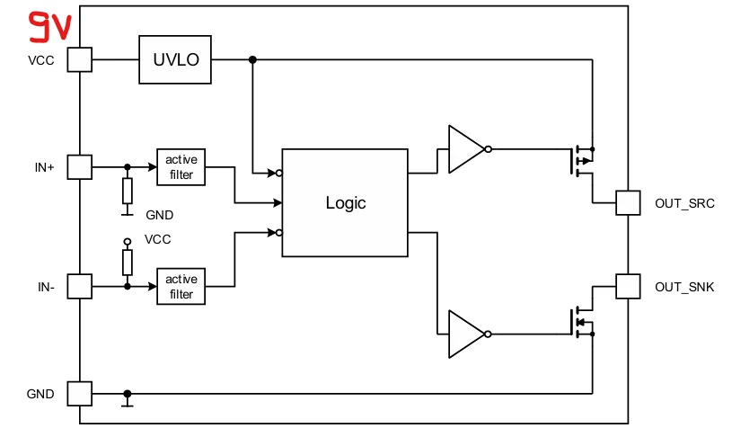
I am using a gate driver IC (1EDN8511BXUSA1) that operates with a 9-10V power supply. The IN- input of the IC is connected to a GPIO pin of the STM32L496, which is internally pulled up to VCC with a 400kΩ resistor (as shown in the picture). At startup, the GPIO pin receives 9V before the initialization process.
 

hzoli_0-1738915171601.png

My question is whether the GPIO pin could be damaged by the 22.5µA injection current that occurs for a short duration during startup?

Thank you for your help.

This topic has been closed for replies.
Best answer by AScha.3

Hi,

1. why not use the IN+ to driver ? ( = pulldown)

2. to be on save side, i would add a diode ( 1n4148 or so) at  gpio/pin --> VDD 3v3 ; to prevent any injection. (2 ct are good investment for 100% not damaging the pin.)

7 replies

Uwe Bonnes
Chief
February 7, 2025

Read the chapter "Absolute maximum ratings" in the datasheetb carefully.  I understand in a way that 9 volt is too high for a FT pin. 3.3 Volt supply plus 4 Volt = 7.3 Volt is the limit in my understanding. Table 20 Table 20. Current characteristics also allows no positive injection.

mƎALLEm
ST Technical Moderator
February 7, 2025

Hello,

Isolate the voltage levels by putting a Mosfet transistor on the GPIO to drive that "IN-" pin. 

To give better visibility on the answered topics, please click "Best answer" on the reply which solved your issue or answered your question.
gbm
Super User
February 7, 2025

From my experience and limited knowledge of STM32 internals, I would not worry at all about 22 uA injection current. The funny thing is that, at least in theory, non-5V-tolerant pins should be safer than 5V-tolerant. In practice, however, there is no big functional difference between them when it comes to SMALL current injections (they do differ internally, however).

My STM32 stuff on github - compact USB device stack and more: https://github.com/gbm-ii/gbmUSBdevice
hzoliAuthor
Associate II
February 10, 2025

Thank you for the quick replies. :)

mƎALLEm
ST Technical Moderator
February 10, 2025

@hzoli wrote:

Thank you for the quick replies. :)


Please accept as solution the comment that answered your question.

Thanks

To give better visibility on the answered topics, please click "Best answer" on the reply which solved your issue or answered your question.
AScha.3
AScha.3Best answer
Super User
February 10, 2025

Hi,

1. why not use the IN+ to driver ? ( = pulldown)

2. to be on save side, i would add a diode ( 1n4148 or so) at  gpio/pin --> VDD 3v3 ; to prevent any injection. (2 ct are good investment for 100% not damaging the pin.)

If you feel a post has answered your question, please click on " Best Answer ".
hzoliAuthor
Associate II
February 15, 2025

Thank you for the help. I have changed the pins, so it has solved the problem.