
Associate II
January 21, 2024
Solved

Generating a PWM that starts high, but ends low after N pulses have been completed.

I have an Arduino Giga (STM32H7) and I'm using the timers to generate PWM's. Everything's working fine, programming is no problem, but I cannot come up with a way to implement what I want. I included a simple visual to describe what I want the output to look like.TIM1TIM8_Visual.png
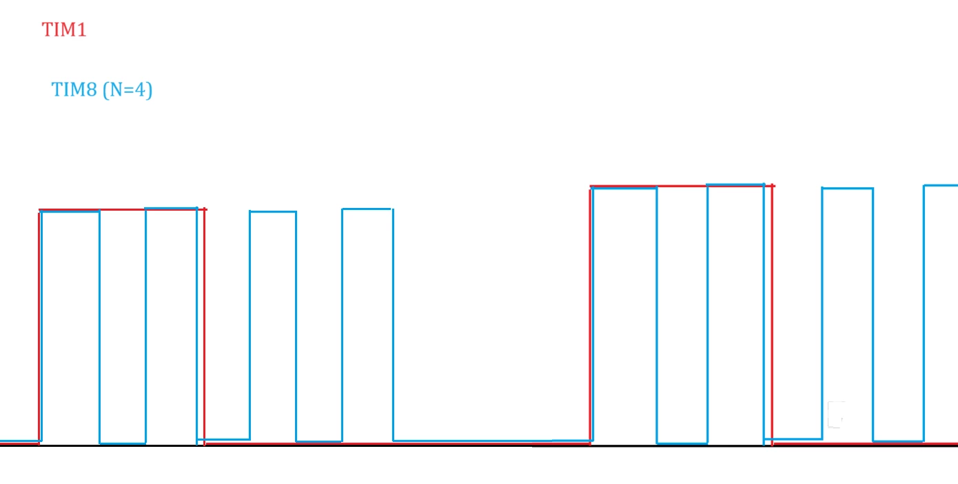


TIM1 is the master timer, it generates a PWM, set as active high (for CNT<CCR). I have a slave TIM8, which should do the following: when TIM1 starts over again/goes high, TIM8 should generate N pulses. The time it takes for N pulses to complete is shorter than the period of TIM1, I want them to retrigger each time TIM1 goes high again. Here's the catch: The pulses should immediately start high, however, once all the pulses have fired, the output should stay low.

If it weren't for the last part, the solution would be simple: TIM1 uses UEV as output trigger, TIM8 takes an internal trigger input from TIM1, set TIM8 to One-Pulse Mode, set the repetition counter to N, and voila, you get bursts of N pulses on each TIM1 high (yes technically the first time it won't trigger, doesn't matter).

However, this will cause the pulses of TIM8 to either start 'delayed', since for CNT<CCR, the output will be low in OPM, or if we flip the polarity, it will start high, but after having finished N pulses, TIM8->CNT=0 (because of OPM), which causes the output to be high...

Can anyone think of a good solution/setup? Again, programming is no issue, it's just finding a way to get this behaviour, if that's even possible... Also, I would prefer not to use interrupts handlers for reasons related to the rest of my program.

This topic has been closed for replies.
TDK
TDKBest answer
January 21, 2024

Very doable with a number of methods

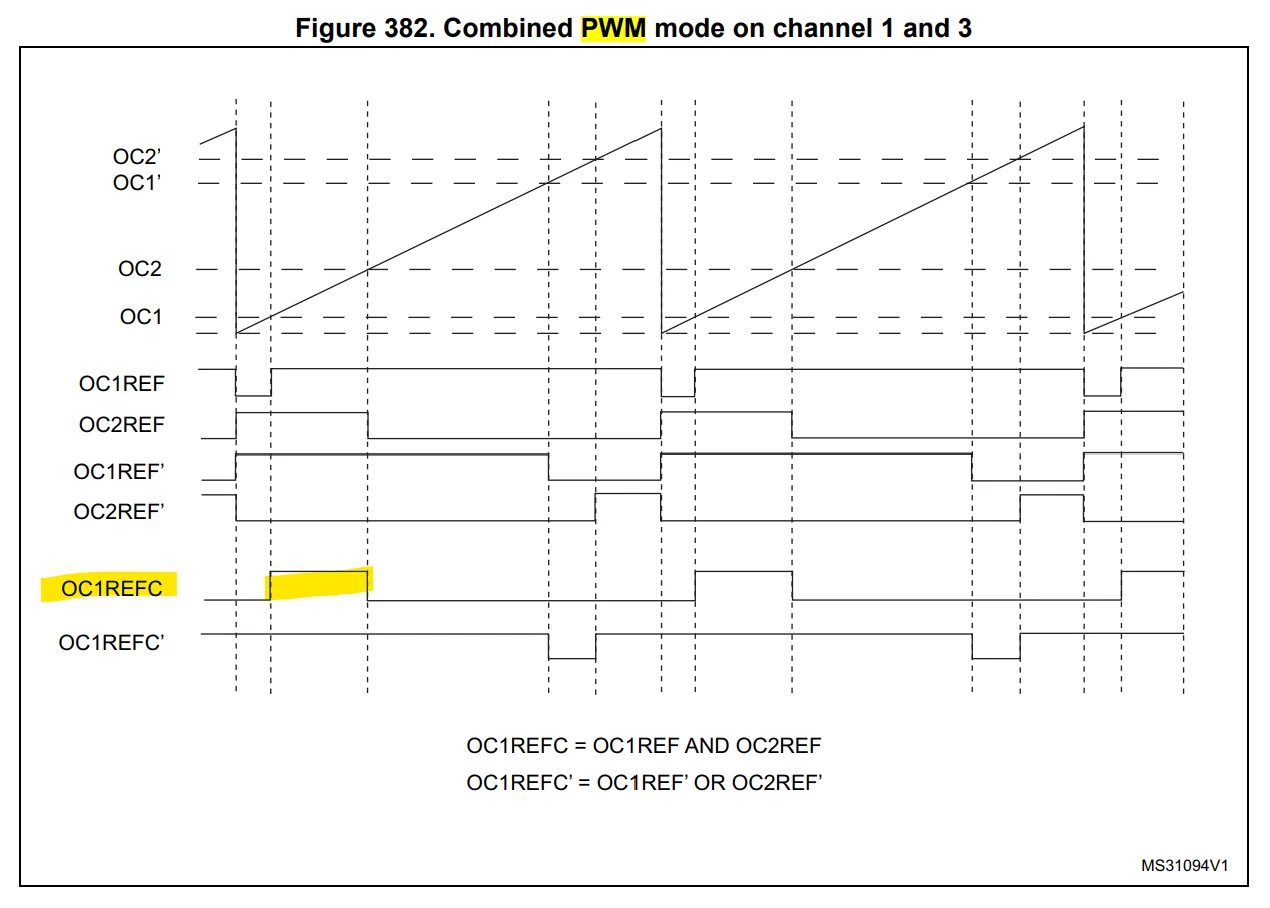
Perhaps the easiest is to use the scheme that almost works except use PWM mode 2 and set it so output is low at CNT=0, high at CNT=1... X, and then low again until it reaches ARR.

TDK_0-1705856593557.png


If you need them to exactly match, you could use TIM8 in gated slave mode to get exactly 4 pulses at the start of each TIM1 period. Can describe this more if you need.


"If you feel a post has answered your question, please click ""Accept as Solution""."

4 replies

TDK
TDKBest answer
January 21, 2024

Very doable with a number of methods

Perhaps the easiest is to use the scheme that almost works except use PWM mode 2 and set it so output is low at CNT=0, high at CNT=1... X, and then low again until it reaches ARR.

TDK_0-1705856593557.png


If you need them to exactly match, you could use TIM8 in gated slave mode to get exactly 4 pulses at the start of each TIM1 period. Can describe this more if you need.


"If you feel a post has answered your question, please click ""Accept as Solution""."
PepijnAuthor
Associate II
January 21, 2024

Ah the combined mode, I hadn't considered that but I'm sure that will work. The single count offset is no problem. Thanks a lot!

waclawek.jan
Super User
August 12, 2024
// Basler: The Basler camera is triggered by a combined PWM mode, to ensure a low level at the end of the frame triggers,
 // while still (almost, at CNT=1) starting high.
 // 12: Combined PWM mode 1 - OC1REF has the same behavior as in PWM mode 1. OC1REFC is the logical OR between OC1REF and OC2REF.
 // 13: Combined PWM mode 2 - OC1REF has the same behavior as in PWM mode 2. OC1REFC is the logical AND between OC1REF and OC2REF.

 TIM8->CCMR1 &= ~TIM_CCMR1_OC1M_Msk; // for TIM8_CH1 - AND
 TIM8->CCMR1 |= (0x13UL << TIM_CCMR1_OC1M_Pos); // 

 TIM8->CCMR1 &= ~TIM_CCMR1_OC2M_Msk; // for TIM8_CH2 - OR
 TIM8->CCMR1 |= (0x12UL << TIM_CCMR1_OC2M_Pos); // 

1. 0x12/0x13 != 12/13

2. TIMx_CCMRx.OCxM bits don't form a continuous bitfield (for historical reasons)

waclawekjan_0-1723483463321.png

JW
