

G431 - Unable to program OB on MCU - first time flash
Among 20-odd PCBs populated with STM32G431CBUx controller, I am facing issue in programming one of them. All the others works fine, with no issues what so ever.
The RDP is set to 0xFF, and the BOOT_LOCK bit was set. I searched through the community posts and tried the following methods.
- Set the BOOT0 pin High and enter through “Under Reset” mode → try to reprogram RDP to 0xAA.
- Try resetting through NRST and then reprogram the option bytes
15:42:24 : ST-LINK SN  : 0670FF564948897767133441
15:42:24 : ST-LINK FW  : V2J33M25
15:42:24 : Board       : NUCLEO-F303RE
15:42:24 : Voltage     : 3.25V
15:42:25 : SWD freq    : 4000 KHz
15:42:25 : Connect mode: Under Reset
15:42:25 : Reset mode  : Hardware reset
15:42:25 : Device ID   : 0x468
15:42:25 : Revision ID : Rev X
15:42:25 : Debug in Low Power mode is not supported for this device.
15:42:25 : UPLOADING OPTION BYTES DATA ...
15:42:25 :   Bank          : 0x00
15:42:25 :   Address       : 0x40022020
15:42:25 :   Size          : 84 Bytes
15:42:25 : UPLOADING ...
15:42:25 :   Size          : 1024 Bytes
15:42:25 :   Address       : 0x8000000
15:42:25 : Read progress:
15:42:25 : Error: Data read failed
15:43:13 : Option byte command : -ob  BOR_LEV=1  BOOT_LOCK=0  nSWBOOT0=0
15:43:13 : qCmd : -ob  BOR_LEV=1  BOOT_LOCK=0  nSWBOOT0=0
15:43:13 : PROGRAMMING OPTION BYTES AREA ...
15:43:13 :   Bank          : 0x00
15:43:13 :   Address       : 0x40022020
15:43:13 :   Size          : 84 Bytes
15:43:14 : Reconnecting...
15:43:15 : Reconnected !
15:43:15 : UPLOADING OPTION BYTES DATA ...
15:43:15 :   Bank          : 0x00
15:43:15 :   Address       : 0x40022020
15:43:15 :   Size          : 84 Bytes
15:43:15 : OPTION BYTE PROGRAMMING VERIFICATION:
15:43:15 : Error: Expected value for Option Byte "BOOT_LOCK": 0x0, found: 0x1
15:43:15 : Error: Option Byte Programming failed Or modified by application after OB_LAUNCH
15:43:15 : Time elapsed during option Bytes configuration: 00:00:01.184
When I tried to read the flash, I expected 0xFF. However, in few areas, I was reading different values.
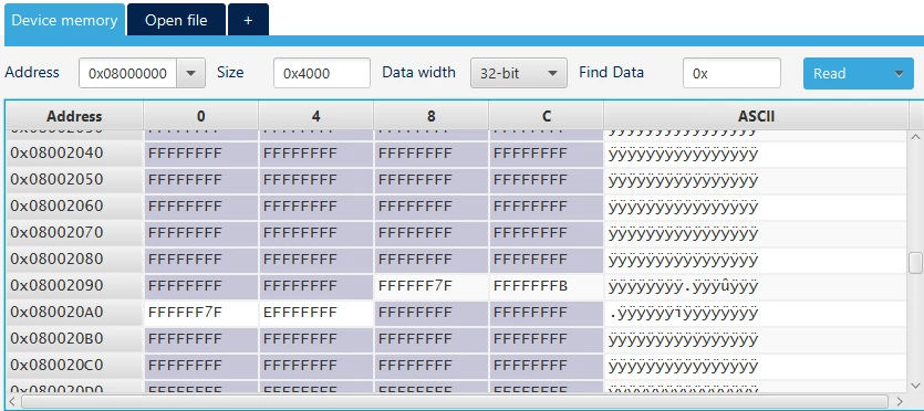
Only once was I able to successfully program the Option bytes and then flash the intended .hex file but the core was locked when I tried to reset the MCU (power cycle).
And sometimes I get the following error.

Does this mean the MCU flash is corrupt? How such issue can happen?
The PCB is powered through a stable and clean power supply (5V), with an on-board LDO converting it to 3.3V. The same HW architecture is also followed in multiple other PCBs with no such errors encountered.
Can improper handling (ESD event during such handling) can result in such a behaviour?
Any leads will be appreciated.