Associate II
November 14, 2024
Solved

G070CBT6 Strange issue with reset line falling down...

Hi, I'm facing a very strange issue with my G070CBT6-based board...


When I start work and power up the board everything works fine for a couple of minutes (let's say 5 minutes ) but later I can observe some disturbances on the reset pin... I connect the oscilloscope and I can see the voltage on the reset pin, after a few minutes of the device operating, starts to fall down slowly and there is some mess on the signal...

Here is an example waveform watched:

Yellow -> 3.3V supply

Blue -> reset line
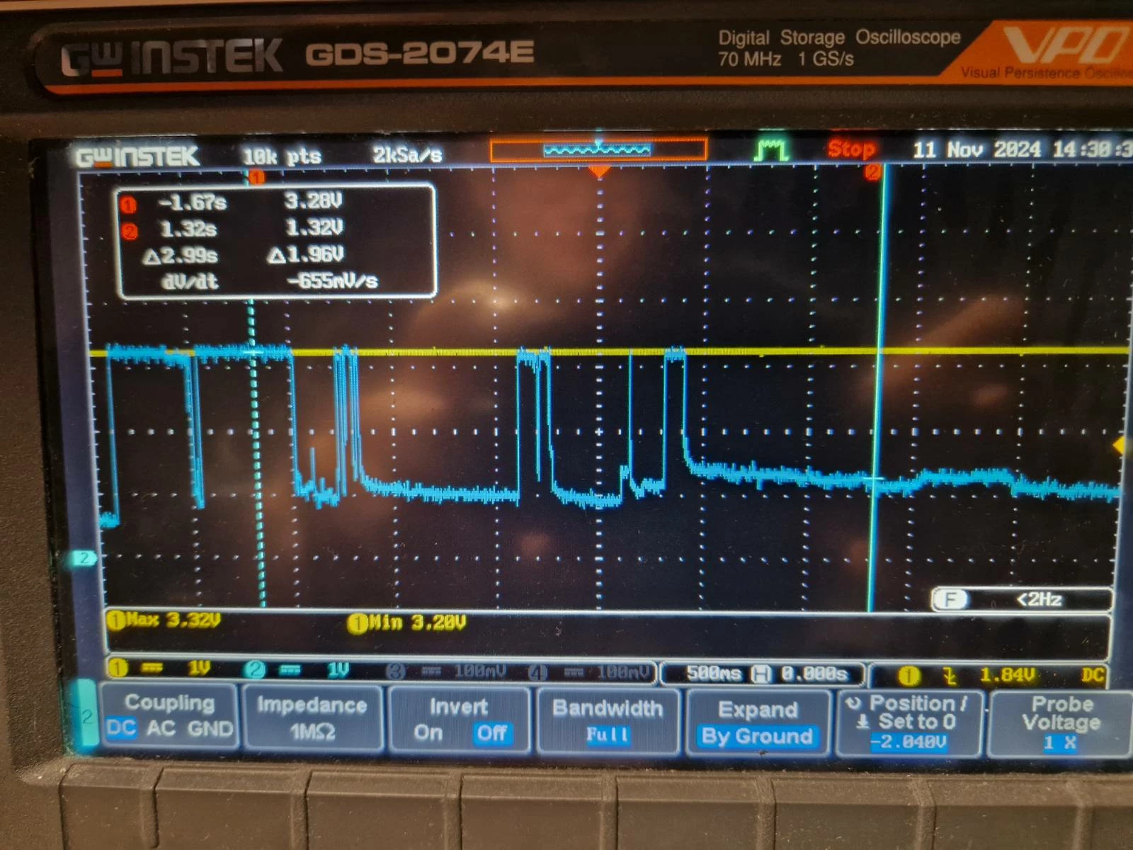
signal-2024-11-11-134804_003.jpeg 

I've tried 3 different pcs of the MCU on the same board and also try soldering bare minimum setup (LDO, MCU, caps, etc.. ) on a totally fresh PCB, and every time the same behavior...

No matter, if the code flashed, is my application code, led blink demo, or totally erased flash.

This is the MCU part of the schematic..Screenshot from 2024-11-14 23-04-40.png  I also tried to pull down the SW_CLK ( there is the BOOT0 also on this pin ) but this ain't help...
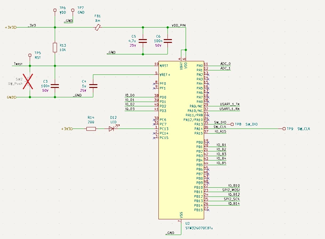
When the issue occurs, I'm not able to do anything with the MCU. It is "held under reset" from the SWD perspective. If I leave the board unpowered for some time to "cool down" it starts operating again, but again only for a couple of minutes... The MCU is not getting hot or something... supply is very stable 3.3V...


Any ideas what is going on with this? I have never had similar issues and I doubt that I broke the MCU during soldering...

This topic has been closed for replies.
mƎALLEm
mƎALLEmBest answer
ST Technical Moderator
November 15, 2024

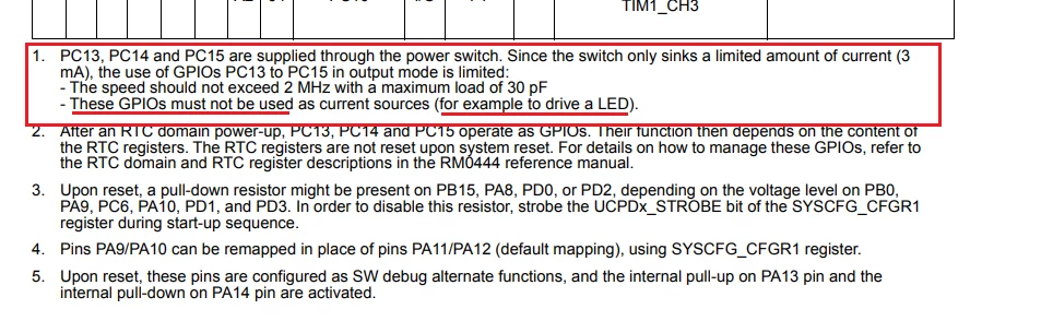
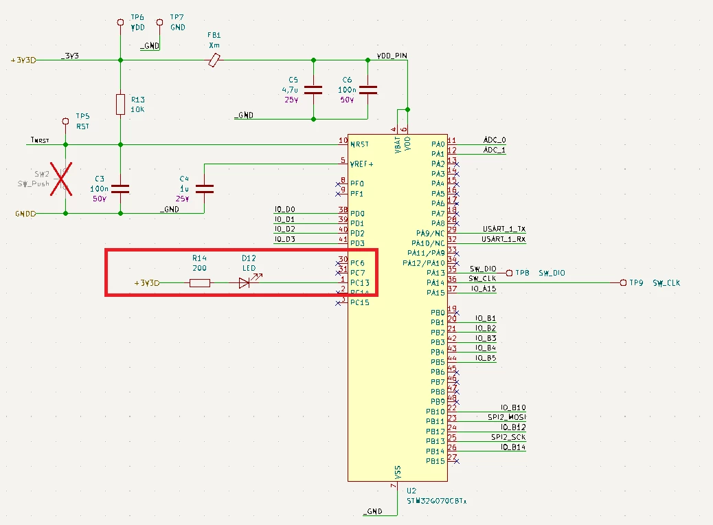
+ the LED on PC13:

SofLit_0-1731656554857.png

From the datasheet:

SofLit_1-1731656727653.png


To give better visibility on the answered topics, please click "Best answer" on the reply which solved your issue or answered your question.

20 replies

mƎALLEm
ST Technical Moderator
November 15, 2024

Hello,

It could be not related to the behavior but please remove that NRST pull-up resistor as there is one internal to the chip:

SofLit_0-1731655544648.png


To give better visibility on the answered topics, please click "Best answer" on the reply which solved your issue or answered your question.
MKowalskiAuthor
Associate II
November 15, 2024

I'm aware of that but this is a 40K resistor so I think that adding 10K externally could only improve the immunity here. 

Anyway, I removed it as You suggested but the problem still exists.

mƎALLEm
ST Technical Moderator
November 15, 2024

@MKowalski wrote:

Anyway, I removed it as You suggested but the problem still exists.


Already said: "It could be not related to the behavior"

To give better visibility on the answered topics, please click "Best answer" on the reply which solved your issue or answered your question.
mƎALLEm
ST Technical Moderator
November 15, 2024

Also there is an issue on VREF+

SofLit_1-1731655845238.png

Vref+ is not connected to an external power source example: VDD!

From NUCLEO schematics:

SofLit_2-1731655939226.png

Please make the nucleo schematics as your reference design.

To give better visibility on the answered topics, please click "Best answer" on the reply which solved your issue or answered your question.
mƎALLEm
mƎALLEmBest answer
ST Technical Moderator
November 15, 2024

+ the LED on PC13:

SofLit_0-1731656554857.png

From the datasheet:

SofLit_1-1731656727653.png


To give better visibility on the answered topics, please click "Best answer" on the reply which solved your issue or answered your question.
MKowalskiAuthor
Associate II
November 15, 2024

 This is something I missed. I'll check. Thanks for pointing. 

waclawek.jan
Super User
November 15, 2024

Hi @mƎALLEm ,

On 'G0, VREF+ does not need to be connected to VDD/VDDA if analog functionality is not used.

waclawekjan_0-1731657155527.png

While the 'G070 officially does not have VREFBUF, those 'G0 which do have it must not connect VREF+ to any external source.

JW

mƎALLEm
ST Technical Moderator
November 15, 2024

Indeed. Only G070 doesn't have an internal VREFBUF. So Vref+ needs to be connected to a power source.

To give better visibility on the answered topics, please click "Best answer" on the reply which solved your issue or answered your question.
MKowalskiAuthor
Associate II
November 15, 2024

I moved the LED to PB9 and connected VREF+ to VDD, but the problem has not been solved.

mƎALLEm
ST Technical Moderator
November 15, 2024

Removed the Pull-up on the reset?

The schematics don't show all the connectivity: USART1, IOs, SPI etc .. Is there something connected to the MCU? 


To give better visibility on the answered topics, please click "Best answer" on the reply which solved your issue or answered your question.
MKowalskiAuthor
Associate II
November 15, 2024

Yes, the pull-up is removed, and there is nothing else connected. 


mƎALLEm
ST Technical Moderator
November 15, 2024

At this stage I cannot help you further.

You said: "supply is very stable 3.3V.."

Try to monitor your power supply again and find if there is a glitch (try to use a trigger).

Check if the power is the origin of that reset by checking that bit:

SofLit_0-1731662490941.png

SofLit_1-1731662566878.png


To give better visibility on the answered topics, please click "Best answer" on the reply which solved your issue or answered your question.
MKowalskiAuthor
Associate II
November 15, 2024

This is the moment of powering up the board with the reset button pressed and released after about 1s...
As You can see it seems not to be related to the power supply...

MKowalski_0-1731663156200.png


mƎALLEm
ST Technical Moderator
November 15, 2024

Monitor PWR RST flag..

To give better visibility on the answered topics, please click "Best answer" on the reply which solved your issue or answered your question.
waclawek.jan
Super User
November 15, 2024

This sounds to me like a hardware problem - bad solder joint on VDD/VSS, short from NRST to neighbouring pins/tracks...?

JW

MKowalskiAuthor
Associate II
November 15, 2024

Yes, I thought so too, but would it be that repeatable? Same problem with 3 different MCUs and on 3 PCBs?

Tomorrow I'll check in a workshop with more professional tools to make sure it's not my fault, but honestly, I hand-assembled hundreds of similar boards and never had such a problem, so I really doubt that now I messed it up 5 times, one after another, exactly the same way... But who knows? maybe....


waclawek.jan
Super User
November 16, 2024

You're right, with multiple pieces of hardware this is unlikely (unless hardware design error).

Have you tried to run some simple software e.g. a plain blinky?

Also, the circuit connected to PD0/PD2, does it account for the 5k1 pulldown mentioned in footnote 3 to pinout table in datasheet?

JW

MKowalskiAuthor
Associate II
November 16, 2024


I've assembled one another board and checked each pad of the MCU with a microscope to be 100% sure there are no issues with soldering. I also did not populate the LED so the PC13 does not drain too much current and this particular board is now operating fine for over an hour. So my simple conclusion is that maybe draining too much current from PC13 could break something inside the MCU, causing this issue with previous boards (each of them was first started with the LED on PC13 enabled). Or indeed some design issues ( like too much heat dissipation on GND pin, what I suspect is also possible after reviewing the layout ) make me mess up soldering so many times...

Anyway the board works fine no matter if there is additional pull-up on the reset pin or Vref+ connected to VDD or not. If the issue will not occur again till the end of the day I will consider this topic closed.

BTW Thanks for help @mƎALLEm and @waclawek.jan

mƎALLEm
ST Technical Moderator
November 16, 2024

Happy to hear that.


@MKowalski wrote:

If the issue will not occur again till the end of the day I will consider this topic closed.


If you will close the topic, please accept the comment that guided you to the solution.

Thanks.

To give better visibility on the answered topics, please click "Best answer" on the reply which solved your issue or answered your question.