

JR2963
Senior II
June 7, 2023
Question

Distorted measurement ADC

  • June 7, 2023
  • 13 replies
  • 5309 views

Hi,

on STM32F303 I use ADC with DMA (12 bit), I measure signals on 3 channels + Vrefin.

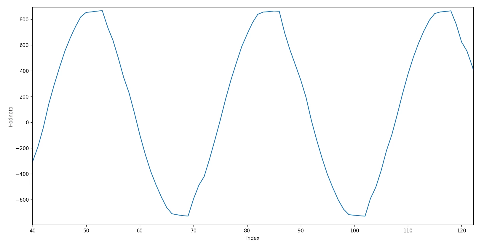
The input signal is pure sine wave 50 Hz (I can see it on scope). But when I measure it with ADC, so there is distored sine wave, I tried to change SAMPLING TIME, and also Sampling frequency. It changed, but this is the best result what I have got, but still distored. Is there any chance how to solve that problem?

There is no saturation, there is reserve in amplitude

_legacyfs_online_stmicro_images_0693W00000dDLA9QAO.png

This topic has been closed for replies.

13 replies

AScha.3
Super User
June 7, 2023

this looks like clipping...

show at input 50% of this amplitude.

If you feel a post has answered your question, please click on " Best Answer ".
waclawek.jan
Super User
June 7, 2023

What's your hardware? Is VREF+ rock stable? Is ground arrangement perfect? Is the AC input perfect? Oscilloscope measurement was directly from signal on mcu pin? DC measurements are stable? Try to measure only one channel. Show individual points (read: where is the continuous curve from?)

JW

JR2963
JR2963Author
Senior II
June 8, 2023

Oscilloscope measurement is directly on mcu pin, DC measurements look stable.

I measure 230/50Hz like that: Maybe the current is to small to charge sampling capacitor in MCU?


_legacyfs_online_stmicro_images_0693W00000dDPH4QAO.pngalso I found this image, but what is the value of Cadc?


_legacyfs_online_stmicro_images_0693W00000dDPHiQAO.png

waclawek.jan
Super User
June 8, 2023


_legacyfs_online_stmicro_images_0693W00000dDPJ5QAO.pngJW

JR2963
JR2963Author
Senior II
June 8, 2023

Thanks! OK it looks like my sampling time is too fast . I have it already on 610_5 cycles, so I have no option to slow it down.

How can I sove it?

  • I can reduce the clock speed of the mcu, but I do now want.
  • Maybe I could measure on the same channel several times in a row and after that change the channel?

Some recommendations?

AScha.3
Super User
June 8, 2023

>looks like my sampling time is too fast 

?? why ?

> I have it already on 610_5 cycles

? 810 cycles ?

too slow. try 8.5 cycles .

and half signal , 2490 -> 1k5 or so, just test !

If you feel a post has answered your question, please click on " Best Answer ".
JR2963
JR2963Author
Senior II
June 8, 2023

This is when I use ADC_SAMPLETIME_601CYCLES_5:


_legacyfs_online_stmicro_images_0693W00000dDPl4QAG.png 

and thisi when 7_5 cycles:


_legacyfs_online_stmicro_images_0693W00000dDPlEQAW.png 

I use ASYNC clock mode

AScha.3
Super User
June 8, 2023

this looks like: beginning clip / limiting and opamp with high feedback -> oscillations , when recover from overdrive.

again: show at input 50% of this amplitude. or use circuit, like i did for mains aquire:


_legacyfs_online_stmicro_images_0693W00000dDQ88QAG.png and use 7.5 cycle .

If you feel a post has answered your question, please click on " Best Answer ".
JR2963
JR2963Author
Senior II
June 8, 2023

And this is with Sync clock/4 with 180_5 cycles:


_legacyfs_online_stmicro_images_0693W00000dDPqTQAW.png 

Also I tried to measure each channel 2 times in row, and use only the second measurement. But it has basically no effect - result is the same

waclawek.jan
Super User
June 8, 2023

Where is the 1.65V coming from, and how does that look like on the oscilloscope?

JW

JR2963
JR2963Author
Senior II
June 8, 2023

I am sorry, now I can see on the scope the signa is not pure wave.I hadn't really seen the distortion before!

Anyway the 1.65 is from OPAMP, but now when the input signal is distored...

I do not understan that, it is 230 Volts throught the isolation transformer directly to the voltage divider...

waclawek.jan
Super User
June 8, 2023

Also, don't you try to use the ADC in differential mode? If so, have you read the Errata?

JW
