

Question
different behaviour of my chip select with different payload size
Hi,
I am working with stm32H743II Board - which define SPI4 block as SPI Master according to the following:
void MX_SPI4_Init(void)
{

 /* USER CODE BEGIN SPI4_Init 0 */

 /* USER CODE END SPI4_Init 0 */

 /* USER CODE BEGIN SPI4_Init 1 */

 /* USER CODE END SPI4_Init 1 */
 /* SPI4 parameter configuration*/
 hspi4.Instance = SPI4;
 hspi4.Init.Mode = SPI_MODE_MASTER;
 hspi4.Init.Direction = SPI_DIRECTION_2LINES;
 hspi4.Init.DataSize = SPI_DATASIZE_8BIT;
 hspi4.Init.CLKPolarity = SPI_POLARITY_LOW;
 hspi4.Init.CLKPhase = SPI_PHASE_1EDGE;
 hspi4.Init.NSS = SPI_NSS_HARD_OUTPUT;
 hspi4.Init.BaudRatePrescaler = SPI_BAUDRATEPRESCALER_8;
 hspi4.Init.FirstBit = SPI_FIRSTBIT_MSB;
 hspi4.Init.TIMode = SPI_TIMODE_DISABLE;
 hspi4.Init.CRCCalculation = SPI_CRCCALCULATION_DISABLE;
 hspi4.Init.CRCPolynomial = 0x7;
 hspi4.Init.NSSPMode = SPI_NSS_PULSE_ENABLE;
 hspi4.Init.NSSPolarity = SPI_NSS_POLARITY_LOW;
 hspi4.Init.FifoThreshold = SPI_FIFO_THRESHOLD_08DATA;
 hspi4.Init.TxCRCInitializationPattern = SPI_CRC_INITIALIZATION_ALL_ZERO_PATTERN;
 hspi4.Init.RxCRCInitializationPattern = SPI_CRC_INITIALIZATION_ALL_ZERO_PATTERN;
 hspi4.Init.MasterSSIdleness = SPI_MASTER_SS_IDLENESS_00CYCLE;
 hspi4.Init.MasterInterDataIdleness = SPI_MASTER_INTERDATA_IDLENESS_00CYCLE;
 hspi4.Init.MasterReceiverAutoSusp = SPI_MASTER_RX_AUTOSUSP_DISABLE;
 hspi4.Init.MasterKeepIOState = SPI_MASTER_KEEP_IO_STATE_ENABLE;
 hspi4.Init.IOSwap = SPI_IO_SWAP_DISABLE;
 if (HAL_SPI_Init(&hspi4) != HAL_OK)
 {
 Error_Handler();
 }
 /* USER CODE BEGIN SPI4_Init 2 */

 /* USER CODE END SPI4_Init 2 */

}
and HAL_SPI_MspInit is defined according to the following:
void HAL_SPI_MspInit(SPI_HandleTypeDef* hspi)
{
 GPIO_InitTypeDef GPIO_InitStruct = {0};
 if(hspi->Instance==SPI4)
 {
 /* USER CODE BEGIN SPI4_MspInit 0 */

 /* USER CODE END SPI4_MspInit 0 */
 /* Peripheral clock enable */
 __HAL_RCC_SPI4_CLK_ENABLE();

 __HAL_RCC_GPIOE_CLK_ENABLE();
 /**SPI4 GPIO Configuration
 PE4 ------> SPI4_NSS
 PE5 ------> SPI4_MISO
 PE6 ------> SPI4_MOSI
 PE12 ------> SPI4_SCK
 */
 GPIO_InitStruct.Pin = GPIO_PIN_4|GPIO_PIN_5|GPIO_PIN_6|GPIO_PIN_12;
 GPIO_InitStruct.Mode = GPIO_MODE_AF_PP;
 GPIO_InitStruct.Pull = GPIO_PULLDOWN;
 GPIO_InitStruct.Speed = GPIO_SPEED_FREQ_HIGH;
 GPIO_InitStruct.Alternate = GPIO_AF5_SPI4;
 HAL_GPIO_Init(GPIOE, &GPIO_InitStruct);

 //HAL_NVIC_SetPriority(SPI4_IRQn, 1, 1);
 //HAL_NVIC_EnableIRQ(SPI4_IRQn);

 /* USER CODE BEGIN SPI4_MspInit 1 */

 /* USER CODE END SPI4_MspInit 1 */
 }
when I'm running a single SPI transaction using
HAL_SPI_TransmitReceive i have different behavior with different payload size:
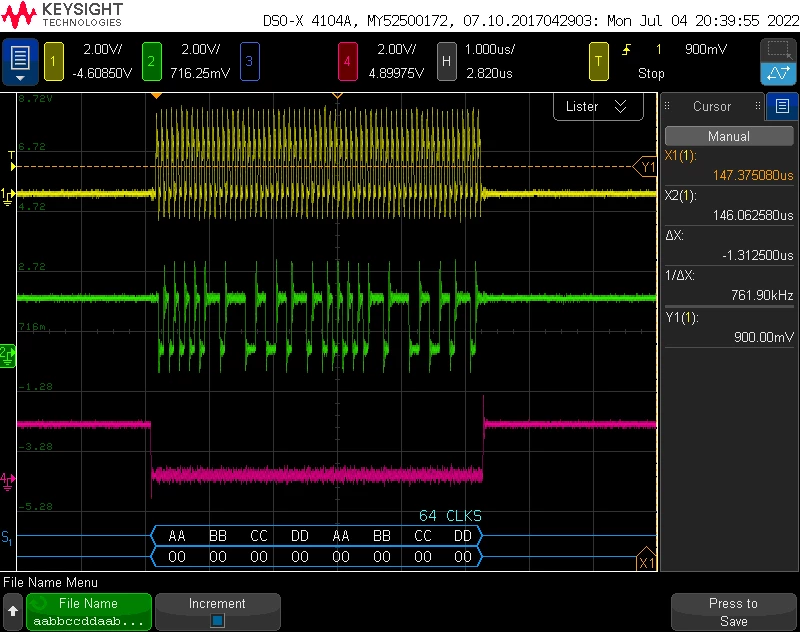
when i am use samll payload = "aabbccddaabbccdd" then i get the following:
but when i am using larger payload = "aabbccddaabbccddaabbccdd" then i get the following: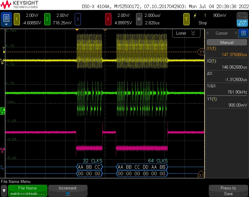
can someone please explain why there is different behavior of the chip select with the number of cycle clocks?
