

Jerry Yung
Associate III
Jul 26, 2019 7:52 AM UTC
Question

Deadtime about PWM

i config TIM with PWM , and insert deadtime , i found the first deadtime is longer than later , this why behave so ?
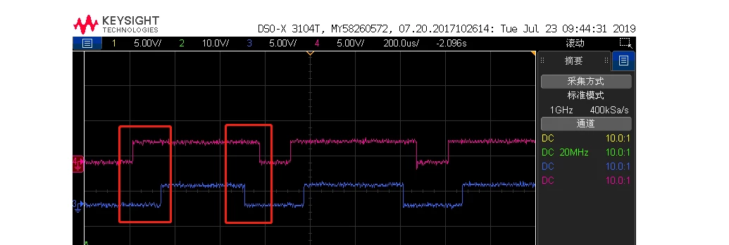

​

0690X000009Z78iQAC.png

This topic has been closed for replies.

5 replies

waclawek.jan
Super User
Jul 26, 2019 12:49 PM UTC

What is exactly the setup (in terms of TIM registers, I don't understand Cube/HAL), and what waveform corresponds to which pin?

JW

Jerry Yung
Associate III
Jul 29, 2019 11:57 AM UTC

pin: CH1N CH1

CCMR: OC1M = 0x06​

CCER: CC1E = 1 ,CC1NE = 1 ,CC1P =0,CC1NP = 1

BDTR: DTG = 0xC8

that's all .

waclawek.jan
Super User
Jul 29, 2019 7:21 PM UTC

If you use PWM mode 1 with CC1P=0 and CC1NP=1, and from reset state set up first CCR1, CCMR1, CCER, ARR, both pins should go high, in timing depending on the order of how these settings are performed, as the counter is not running yet, CNT == 0, and in PWM1mode, while CNT<CCR1, the non-inverted output is active.

In other words, the first two rising edges are most probably artefact from the setup process. You may try to set up everything except CCER, and then enable both channels in a single write of CCER, before starting the counter (CR1.CEN=1). You should then see the first two edges to rise simultaneously, and then the rest of the waveform as expected.

JW

Jerry Yung
Associate III
Jul 30, 2019 12:13 PM UTC

yes, the first two edges rise ​simultaneously,

but I want a deadtime between the firse two edges

waclawek.jan
Super User
Jul 30, 2019 12:19 PM UTC

Try to set CNT to ARR-1 just before enabling the timer.

JW