
Associate II
September 5, 2026
Question

Damaged STM32H743IIT6 on custom board

  • September 5, 2026
  • 8 replies
  • 42 views

I have created a dev board based on the STM32H743IIT6 MCU. On first power up I have managed to destroy two MCUs and I cant figure out what is killing them. On first power up 3V3 is immediately shorted to GND, after removing the MCU the pins are permanently shorted.

Here is my schematic. The only changes I have made from the physical PCB is adding 10K pull up to PDR_ON, 10K in line from VBUS to the MCU and connecting the VCAP pins. 
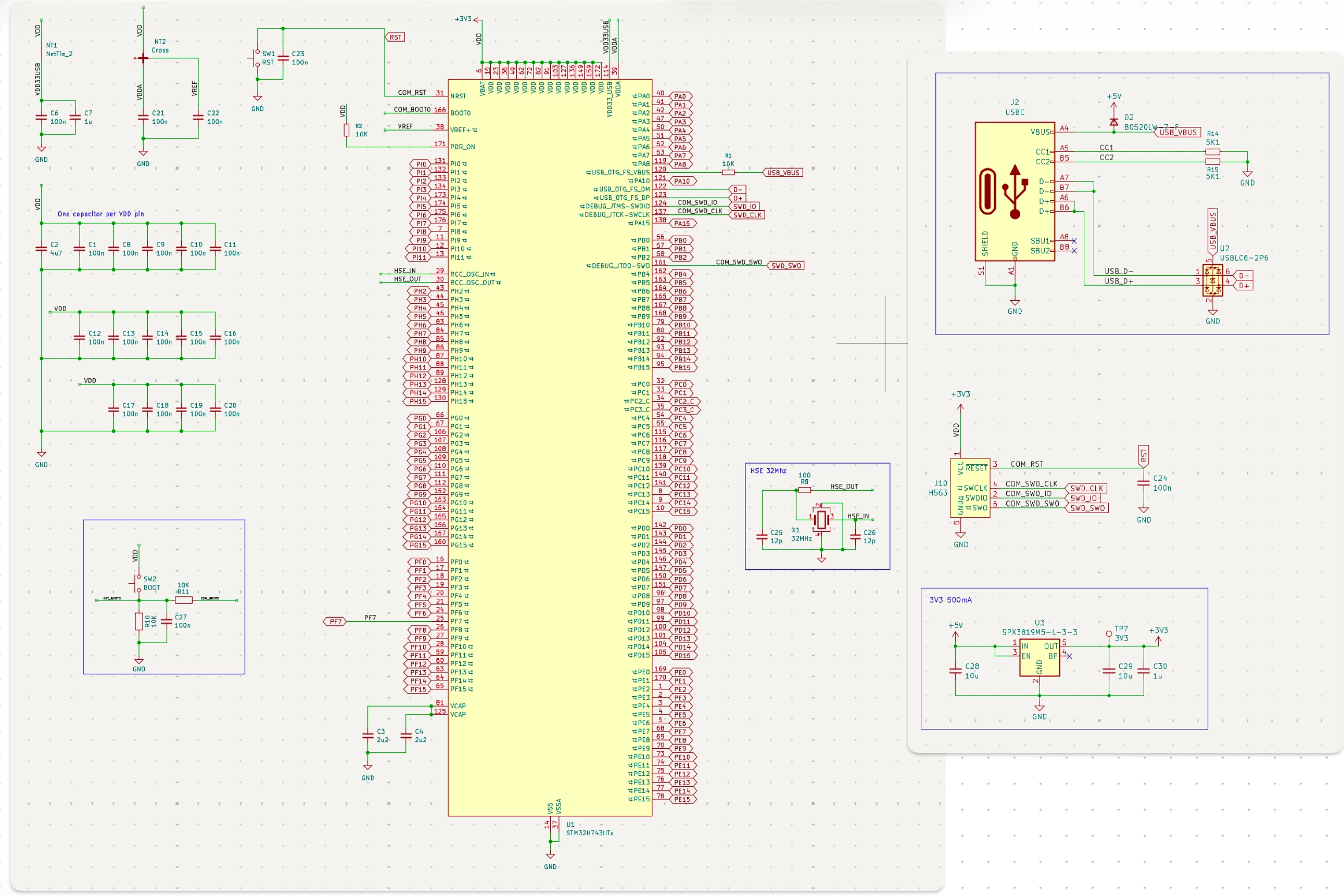
Does anything stand out in the schematic?

I have created modules from multiple STM MCUs(F1,G0,G4,WB,H5,N6) and this is the first time I am running into a power issue with a PCB.

8 replies

Associate II
September 5, 2026

on your schematic you only have pin 14 connected to VSS when the datasheet for the Figure 9. LQFP176 pinout shows many VSS  if you only use one pin for VSS its a problem, the SPX3819 linear regulator has low dropout of 340mV  suggest you put the MCU into reset (low current draw) set your PSU to limit current to 50mA and set voltage to 3.65V max and turn on then try to find any fault, you could also power up the board without the MCU present and test voltage of VDD pads

neil1106Author
Associate II
September 5, 2026

The VSS pin is shared with all GND pins on the footprint (standard footprint with Kicad for this MCU). This board is actually 2 parts, power and USB on a carrier and the MCU and decoupling/crystal on another. I tested each pad without the MCU soldered and the voltages are correct.

Visitor II
September 5, 2026

You shouldn't use the SPX3819M5, I've used it before. I recommend using the AP7361C or LM2514. 

Associate II
September 5, 2026

Ah got it you are using the USB to power the SPX3819M5-L-3-3/TR regulator that will easily fry the MCU  either if a) the regulator is not 3.3V  b) the regulator is broken c) the GND connection (VSS) pin 2 of the regulator is floating (not soldered on properly). 

If you can use a low voltage bench power supply in place of the USB suggest you put the MCU into reset (low current draw) set your PSU to limit current to 50mA and set voltage to 3.65V max and turn on then try to find any fault.

AScha.3
Super User
September 5, 2026

> On first power up 3V3 is immediately shorted to GND

So just 2 things to check:

  • verify the 3v3 never going > 3v5 , at power up etc. ; check without cpu and scope
  • check orientation of cpu on board ! Sounds silly, but happens more often than you think.  - > show pic of cpu on board.


+

Where VDDA and VDD_USB are coming from? connect both direct to VDD.

If you feel a post has answered your question, please click on " Best Answer ".
neil1106Author
Associate II
September 5, 2026

Where VDDA and VDD_USB are coming from? connect both direct to VDD.

Top left of schematic has net ties for all the power rails. In the image below the bodge wire is to connect the VCAP pins. The decoupling caps are under the MCU on the other side of the pcb.


Associate II
September 5, 2026

your schematic is well drawn, VBUS these days can exceed 5V a safer way to use USB_OTG_FS_VBUS pin to test VBUS is like this:-


MM..1
Super User
September 6, 2026

After removing is shorted = what before = MCU was never powered = no destroy
And connecting VCAPs you read where ? Plus form PCB photo VCAPs ground is one via to bottom or is PCB 4 layer ??