
DAC not working - Get no current/voltage from it.
Hi!
I have a STM32F373VBT and when I enable the DAC output, then I get only 0.06V as output, no matter what DAC value I send to the DAC.. I don't understand why i get only fixed 0.06V as output for both of these DAC outputs.
First if all, the DAC outputs are going to drive a OP-amp. This OP-amp will transform 0-3.3V to 0-20mA output by help of 24V voltage source.
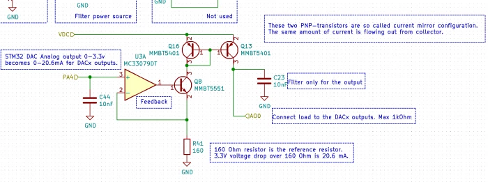 I have connected the DAC pins here to the OP-amp.
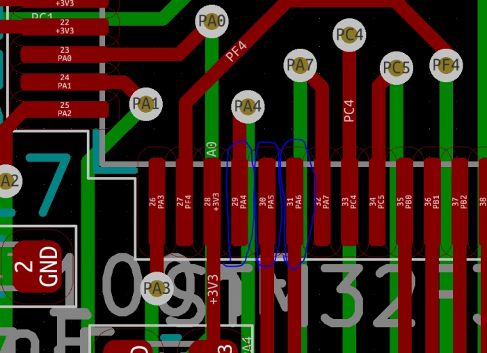
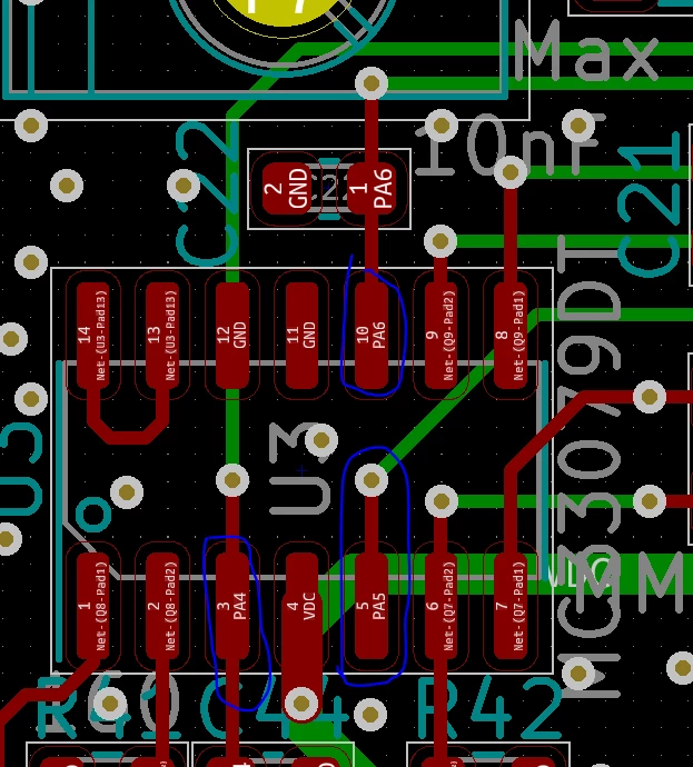
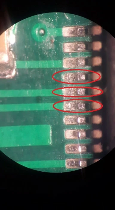
And there are no solder bridge between the MCU's pinns.
Not even them are attached to the GND. I have checked with a DMM.
I have placed the DAC-control code here.
static DAC_HandleTypeDef* hanalog1;
static DAC_HandleTypeDef* hanalog2;
static uint16_t dac_values[3] = {0};

void STM32_PLC_Start_Analog_Output(DAC_HandleTypeDef* hdac1, DAC_HandleTypeDef* hdac2, TIM_HandleTypeDef* htim6) {
	HAL_TIM_Base_Start(htim6); /* The Analog Outputs (DAC) are triggered by TIM6 */
	if(HAL_DAC_Start(hdac1, DAC1_CHANNEL_1) != HAL_OK)
		Error_Handler();
	if(HAL_DAC_Start(hdac1, DAC1_CHANNEL_2) != HAL_OK)
		Error_Handler();
	if(HAL_DAC_Start(hdac2, DAC2_CHANNEL_1) != HAL_OK)
		Error_Handler();
	hanalog1 = hdac1;
	hanalog2 = hdac2;
}

void STM32_PLC_Analog_Output_Set(uint8_t i, uint16_t output) {
	switch(i){
	case 0:
		HAL_DAC_SetValue(hanalog1, DAC1_CHANNEL_1, DAC_ALIGN_12B_R, output);
		dac_values[0] = output;
		break;
	case 1:
		HAL_DAC_SetValue(hanalog1, DAC1_CHANNEL_2, DAC_ALIGN_12B_R, output);
		dac_values[1] = output;
		break;
	case 2:
		HAL_DAC_SetValue(hanalog2, DAC2_CHANNEL_1, DAC_ALIGN_12B_R, output);
		dac_values[2] = output;
		break;
	}
}

uint16_t STM32_PLC_Analog_Output_Get(uint8_t i) {
	return dac_values[i];
}
And I control the DAC like this.
STM32_PLC_Start_Analog_Output(&hdac1, &hdac2, &htim6); // This runs only once
 .
 .
 .
	 STM32_PLC_Analog_Output_Set(0, d0);
	 STM32_PLC_Analog_Output_Set(1, d1);
	 STM32_PLC_Analog_Output_Set(2, d2);
	 d0 += 10;
	 d1 += 20;
	 d2 += 30;
	 if(d0 >= 4095)
		 d0 = 0;
	 if(d1 >= 4095)
		 d1 = 0;
	 if(d2 >= 4095)
		 d2 = 0;
TIM6, which is the trigger for DAC, is decleared.
static void MX_TIM6_Init(void)
{

 /* USER CODE BEGIN TIM6_Init 0 */

 /* USER CODE END TIM6_Init 0 */

 TIM_MasterConfigTypeDef sMasterConfig = {0};

 /* USER CODE BEGIN TIM6_Init 1 */

 /* USER CODE END TIM6_Init 1 */
 htim6.Instance = TIM6;
 htim6.Init.Prescaler = 18;
 htim6.Init.CounterMode = TIM_COUNTERMODE_UP;
 htim6.Init.Period = 0xffff;
 htim6.Init.AutoReloadPreload = TIM_AUTORELOAD_PRELOAD_DISABLE;
 if (HAL_TIM_Base_Init(&htim6) != HAL_OK)
 {
 Error_Handler();
 }
 sMasterConfig.MasterOutputTrigger = TIM_TRGO_UPDATE;
 sMasterConfig.MasterSlaveMode = TIM_MASTERSLAVEMODE_DISABLE;
 if (HAL_TIMEx_MasterConfigSynchronization(&htim6, &sMasterConfig) != HAL_OK)
 {
 Error_Handler();
 }
 /* USER CODE BEGIN TIM6_Init 2 */

 /* USER CODE END TIM6_Init 2 */

}
and also the DAC's itself.
static void MX_DAC1_Init(void)
{

 /* USER CODE BEGIN DAC1_Init 0 */

 /* USER CODE END DAC1_Init 0 */

 DAC_ChannelConfTypeDef sConfig = {0};

 /* USER CODE BEGIN DAC1_Init 1 */

 /* USER CODE END DAC1_Init 1 */
 /** DAC Initialization
 */
 hdac1.Instance = DAC1;
 if (HAL_DAC_Init(&hdac1) != HAL_OK)
 {
 Error_Handler();
 }
 /** DAC channel OUT1 config
 */
 sConfig.DAC_Trigger = DAC_TRIGGER_T6_TRGO;
 sConfig.DAC_OutputBuffer = DAC_OUTPUTBUFFER_ENABLE;
 if (HAL_DAC_ConfigChannel(&hdac1, &sConfig, DAC_CHANNEL_1) != HAL_OK)
 {
 Error_Handler();
 }
 /** DAC channel OUT2 config
 */
 if (HAL_DAC_ConfigChannel(&hdac1, &sConfig, DAC_CHANNEL_2) != HAL_OK)
 {
 Error_Handler();
 }
 /* USER CODE BEGIN DAC1_Init 2 */

 /* USER CODE END DAC1_Init 2 */

}

/**
 * @brief DAC2 Initialization Function
 * @param None
 * @retval None
 */
static void MX_DAC2_Init(void)
{

 /* USER CODE BEGIN DAC2_Init 0 */

 /* USER CODE END DAC2_Init 0 */

 DAC_ChannelConfTypeDef sConfig = {0};

 /* USER CODE BEGIN DAC2_Init 1 */

 /* USER CODE END DAC2_Init 1 */
 /** DAC Initialization
 */
 hdac2.Instance = DAC2;
 if (HAL_DAC_Init(&hdac2) != HAL_OK)
 {
 Error_Handler();
 }
 /** DAC channel OUT1 config
 */
 sConfig.DAC_Trigger = DAC_TRIGGER_T6_TRGO;
 sConfig.DAC_OutputBuffer = DAC_OUTPUTBUFFER_ENABLE;
 if (HAL_DAC_ConfigChannel(&hdac2, &sConfig, DAC_CHANNEL_1) != HAL_OK)
 {
 Error_Handler();
 }
 /* USER CODE BEGIN DAC2_Init 2 */

 /* USER CODE END DAC2_Init 2 */

}
Here is my Main.c file
If I disable these, then DAC works. It must be a bug or something?
I can send you the project if you want. Just tell me how.
/* USER CODE END SysInit */

 /* Initialize all configured peripherals */
 MX_GPIO_Init();
 MX_DAC1_Init();
 MX_DAC2_Init();
 //MX_RTC_Init();
 MX_SPI2_Init();
 //MX_TIM2_Init();
 //MX_TIM5_Init();
 MX_SPI1_Init();
 //MX_TIM4_Init();
 //MX_SDADC1_Init();
 //MX_SDADC2_Init();
 //MX_SDADC3_Init();
 //MX_TIM19_Init();
 //MX_CAN_Init();
 //MX_USART1_UART_Init();
 MX_TIM6_Init();
 //MX_TIM12_Init();
 //MX_TIM13_Init();
 //MX_TIM16_Init();
 //MX_USB_DEVICE_Init();
 //MX_FATFS_Init();
 //MX_TIM14_Init();
 /* USER CODE BEGIN 2 */
