Associate
January 6, 2025
Solved

CAN Rx Interrupt not triggering in Normal mode (worked in Loopback mode)

  • January 6, 2025
  • 15 replies
  • 3432 views

Hi

I am trying to communicate CAN. I am using two boards Nucleo-G474RE and Nucleo-H755ZI-Q and two MCP2551 as transceiver.
On either side, program works for External loop back configuration. ( I did step by step debug to ensure the transmitting data is getting received or not).

But I am not getting the interrupt when in normal mode. I also tried using a single board with shorting tx and rx of the transceiver and also using two boards.
What might be the issue?

I have only attached the IOC file and main.c file for Nucleo-H755ZI-Q and it is similar for Nucleo-G474RE also.
This topic has been closed for replies.
Best answer by mƎALLEm

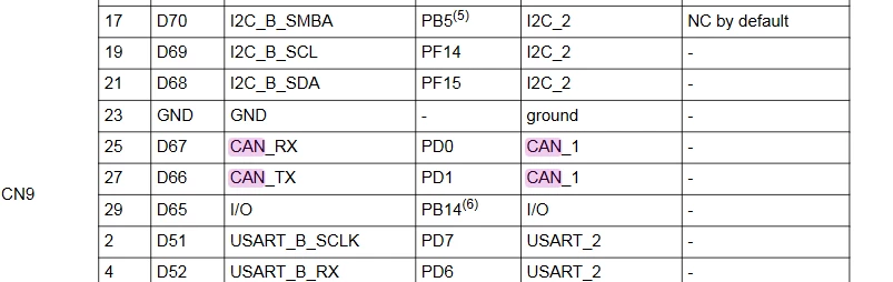
1- In the manual gives you an example of CAN pin usage (PD0 and PPD1) and it's not a restriction:

SofLit_0-1736754994444.png

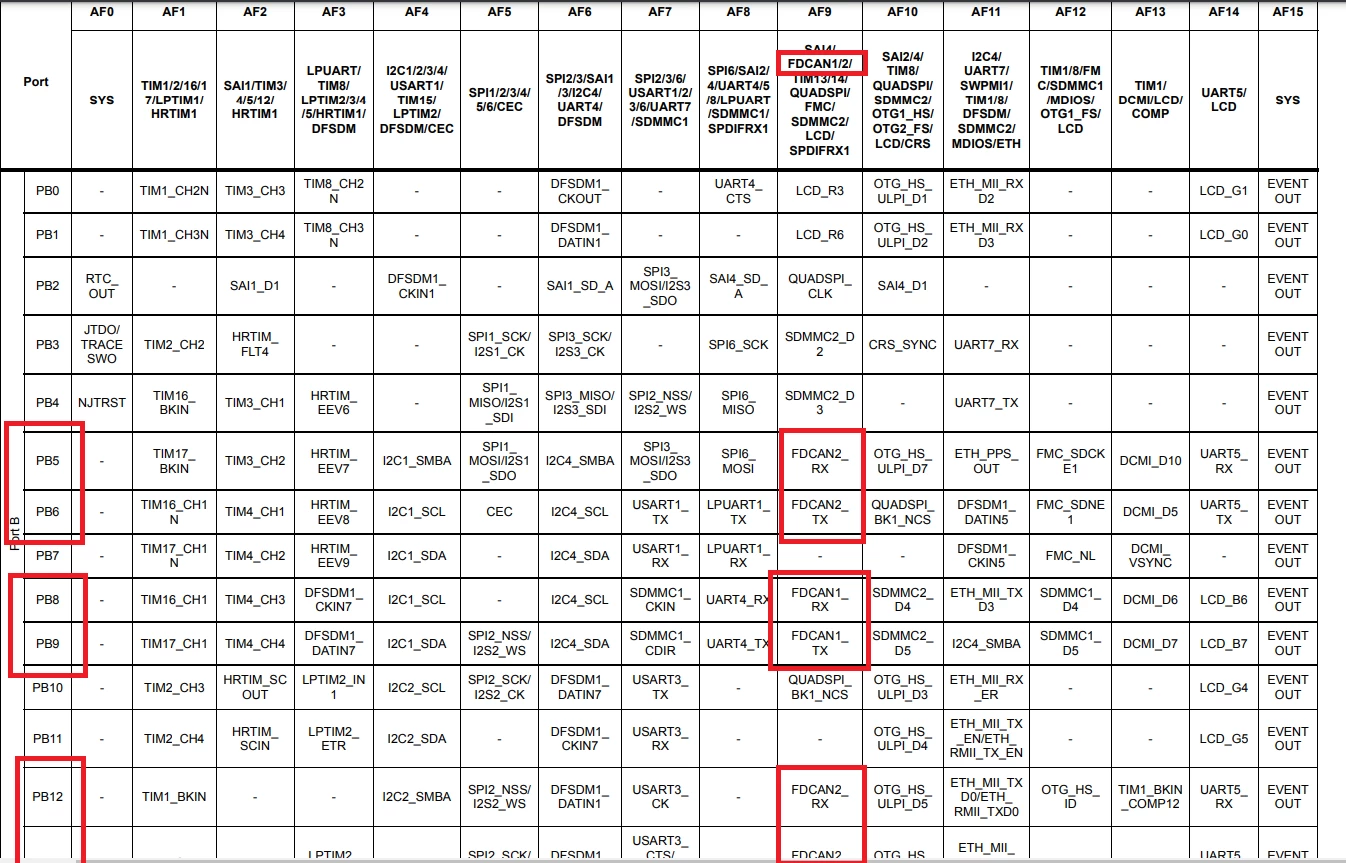
To find the CAN pin usage possibilities the datasheet is the right document to refer to:

SofLit_1-1736755290610.png

Many possibilities for FDCAN1 and FDCAN2 offer to you (make a search in the document). But you need to select a pin not used in the board i.e. it's a free pin and not connected to nothing else in the schematics.

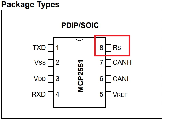
2- And this transceiver pin needs to be pulled to the ground:

SofLit_2-1736755434170.png

I see from your screen shot you are using shields but better to double check with a multimeter (in continuity mode with transceivers are powered off).


15 replies

mƎALLEm
ST Technical Moderator
January 6, 2025

Hello,

Better to share the two projects for G4 and H7.

To me, I have a doubt regarding the bitrate:

SofLit_0-1736176718625.png

Are you sure this is the intended CAN bitrate? 115440 ? this is not a regular CAN bitrate.

if yes do you have the same bitrate on both CAN nodes?

Also, it's not recommended to use HSI for CAN communication. You need an external precise clock either a crystal or crystal oscillator:

SofLit_1-1736176925800.png

Need also to share your schematics including the transceiver.


To give better visibility on the answered topics, please click "Best answer" on the reply which solved your issue or answered your question.
Karl Yamashita
Principal
January 6, 2025

If you can get it to work in loopback mode but not normal mode, then it probably a hardware issue.

You have not indicated if you used terminating resistors when connecting the MCP2551?

If a reply has proven helpful, click on Accept as Solution so that it'll show at top of the post.CAN Jammer an open source CAN bus hacking toolCANableV3 Open Source
AswinAuthor
Associate
January 7, 2025

Hi

Thanks for the reply.

Sorry I didn't use the terminating resistor. Let me try with that and update you.
Just a small query, this project is to test the CAN communication. Is it possible to do this with one board and 2 transceiver ( loopbacking TX and RX of the second transceiver so that whatever data you transmit is getting received ) ? 

Aswin_0-1736228739429.png

its a hand-drawn schematic.

Karl Yamashita
Principal
January 7, 2025

Yes you can use 1 Nucleo that has at least 2 CAN controllers. You can't loop the TX and RX on the CAN transceiver. Technically you need two 120 ohm resistors on either ends of the CAN bus lines.


This link has an image showing the terminating resistors at each end with Node A and Node B connected to the bus.

https://www.rs-online.com/designspark/a-can-bus-primer-part-1-introduction

If a reply has proven helpful, click on Accept as Solution so that it'll show at top of the post.CAN Jammer an open source CAN bus hacking toolCANableV3 Open Source
AswinAuthor
Associate
January 7, 2025

How am I supposed to check the communication? I don't have any logic analyzers. I can check whether the transmitted data is getting received.

Aswin_1-1736237463547.png

I apologize for asking too much question. Did you mean to say that this might work? 1 nucleo and 2 CAN controllers.

mƎALLEm
ST Technical Moderator
January 7, 2025

Hello;

No this is not the right HW connection:


@Aswin wrote:

Aswin_1-1736237463547.png

.


Here you connected two transceivers to the same CAN instance. You need two CAN/FDCAN instances for example CAN1 and CAN2 and two transceivers. For both MCUs you have two CAN instances each.

This is the minimum hardware and connection to establish between two CAN nodes:

https://community.st.com/t5/stm32-mcus/stm32-fdcan-running-at-8-mb-s-on-nucleo-boards/ta-p/730281?lightbox-message-images-730281=90488iD4EA082CEF3B11D9

You can use two CAN instances of the same board.

You didn't attach your two projects for both boards and you didn't tell if you changed the clock source from HSI to HSE.

As you are using Nucleo board, you can read this article how to use STLINK MCO as a precise clock source for CAN.


To give better visibility on the answered topics, please click "Best answer" on the reply which solved your issue or answered your question.
AswinAuthor
Associate
January 12, 2025

Hi Sorry for the delayed response.

I tried with configuring two different CAN in a single board. Still there is no progress. I have attached the cube project files.
I used Nucleo-H755ZI-Q. 
I have some confusion regarding the TX,RX pins of the FDCAN in the MCU. 

Aswin_0-1736704157186.png


Karl Yamashita
Principal
January 12, 2025

You only show TX/RX connected to the MCP2551.

Is the MCP2551 VDD connected to 5V and VSS connected to ground? Is the Rs pin connected to ground as well?

If a reply has proven helpful, click on Accept as Solution so that it'll show at top of the post.CAN Jammer an open source CAN bus hacking toolCANableV3 Open Source
AswinAuthor
Associate
January 12, 2025

Aswin_0-1736708223863.png

Yes, since MCP2551 powering connections are obvious I didn't mention in the connection drawing.
VCC is connected to 5V and GND pins are shorted along with the board GND.
You did mention about Rs pin:  There is no Rs pin ; is it a typo for 'Rx' - if yes then I didnt connect it to the ground

Karl Yamashita
Principal
January 12, 2025

The MCP2551 does indeed have an Rs pin. You didn't mention that you are using a custom PCB board with the MCP2551 on it. If you look at the schematic for that PCB board, the Rs pin is grounded. 

The next step is to get a oscilloscope to see if you are getting CAN bus messages transmitted. Then you can determine if it's an Rx or Tx issue.

If a reply has proven helpful, click on Accept as Solution so that it'll show at top of the post.CAN Jammer an open source CAN bus hacking toolCANableV3 Open Source
AswinAuthor
Associate
January 12, 2025

OK. Let me try using oscilloscope.
Can you please confirm whether I am using the right pin or not?
In  the manual, I can only find 2 pins for CAN. Initially i used it for FDCAN1 and later on I was confused which pin i will be using for FDCAN2.
Then when i configured it, by default it was gave me PB12 and PB11 pins. I did try with that. Then I searched in the CUBE IDE itself for alternative pins (Ctrl + hold mouse - alternative pin configuration will blink in the pinout). It showed me PB5 and PB6. I did try with that but it didnt help.

mƎALLEm
mƎALLEmBest answer
ST Technical Moderator
January 13, 2025

1- In the manual gives you an example of CAN pin usage (PD0 and PPD1) and it's not a restriction:

SofLit_0-1736754994444.png

To find the CAN pin usage possibilities the datasheet is the right document to refer to:

SofLit_1-1736755290610.png

Many possibilities for FDCAN1 and FDCAN2 offer to you (make a search in the document). But you need to select a pin not used in the board i.e. it's a free pin and not connected to nothing else in the schematics.

2- And this transceiver pin needs to be pulled to the ground:

SofLit_2-1736755434170.png

I see from your screen shot you are using shields but better to double check with a multimeter (in continuity mode with transceivers are powered off).


To give better visibility on the answered topics, please click "Best answer" on the reply which solved your issue or answered your question.