Ozzys
Associate
January 9, 2020
Question

Can not connect to target

  • January 9, 2020
  • 10 replies
  • 3699 views

0690X00000BvnAcQAJ.png0690X00000BvnAXQAZ.png0690X00000BvnA3QAJ.jpg0690X00000Bvn9yQAB.jpg0690X00000Bvn9tQAB.jpg0690X00000Bvn9oQAB.jpg

    This topic has been closed for replies.

    10 replies

    Ozzys
    OzzysAuthor
    Associate
    January 9, 2020

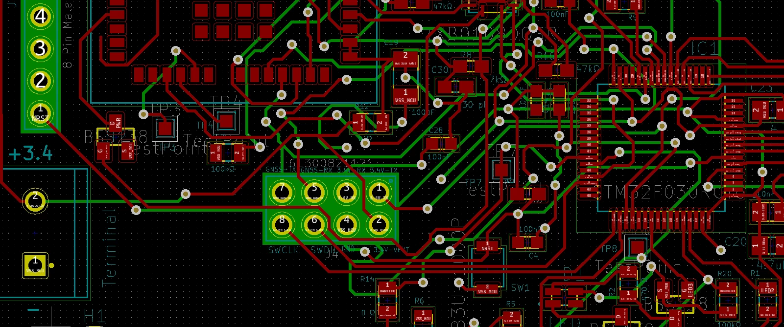
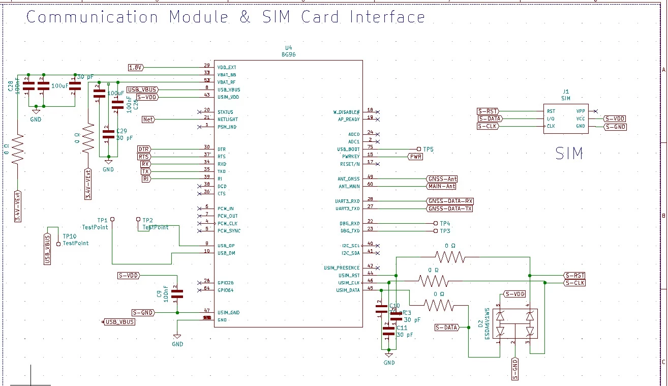
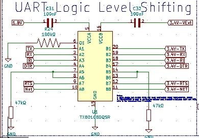
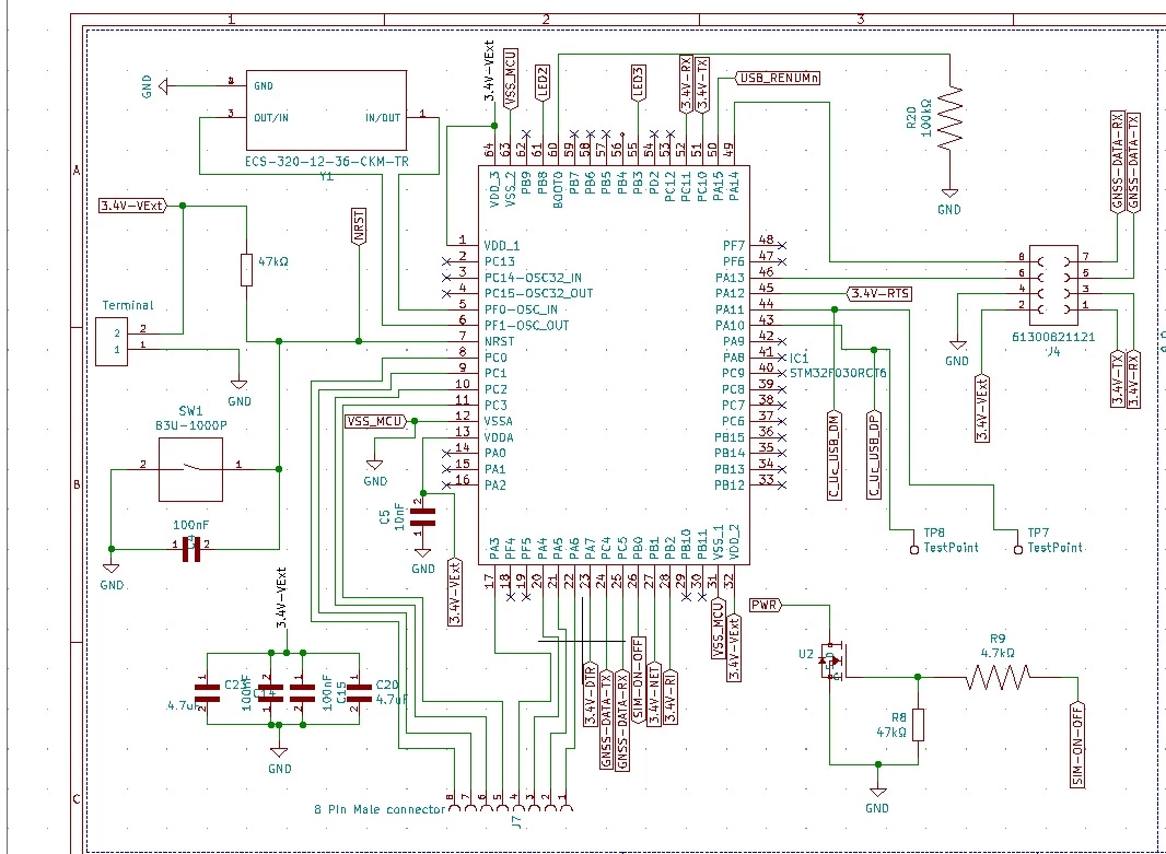
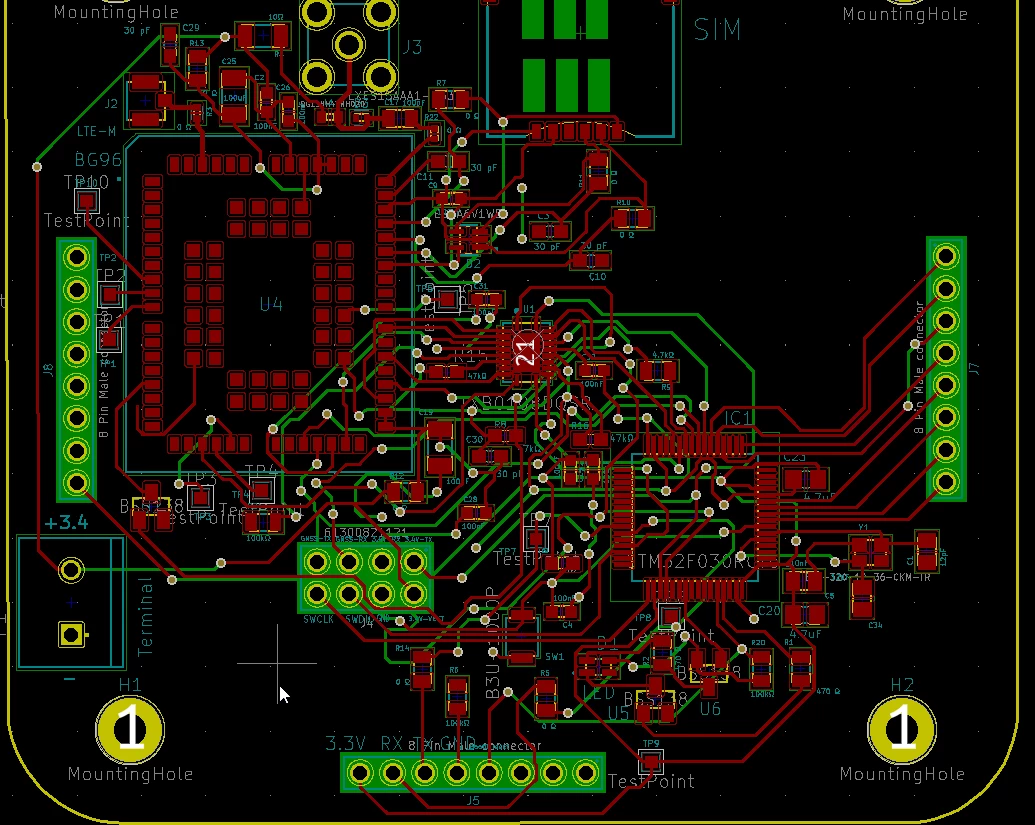
    Hi guys, this is my first question on this community, I really did a lot of work on this pcb, I tried to make a custom made PCB board with the STM32F030RCT, So I tried to program the microcontroller with ST-LINKv2 programmer via SWD& SWDIO. I download the needed driver for the st-linkv2 but I still can not program the microcontroller, the output = 'Can not connect to target' using stm32CUBEIDE really tried everything to program it. I even tried the usb to uart cp2104 to program but even that did not work. All VCC are correct 3.3 Volts and there is no shortcircuit. I measured all VCC and the RST pin and boot0 pin and the capacitors are correct.

    Tesla DeLorean
    Guru
    January 9, 2020

    Make sure the part orientation is correct, Don't confuse ejector pin marks for pin 1 mark.

    The external ST-LINK/V2 pod needs power on Pin 1 or 2 for the buffer logic.

    The secondary signs-of-life method is to have BOOT0 High, and send an 0x7F data pattern at 9600 8E1 (Even Parity) and observe a 0x79 response.

    Use RealTerm in Hex mode, and look at AN2606 for pins used by the boot loader.

    Tips, Buy me a coffee, or three.. PayPal Venmo (See Profile) Up vote any posts that you find helpful, it shows what's working..
    Ozzys
    OzzysAuthor
    Associate
    January 9, 2020

    The first signs-of-life methode1 : Pin 1 is marked here, is this right? The datasheet was bit confusing but this seems right to me? This seems to be right, I connected the 3.3V and GND as shown in the picture, also the SWDIO and SWCLK and reset pin.

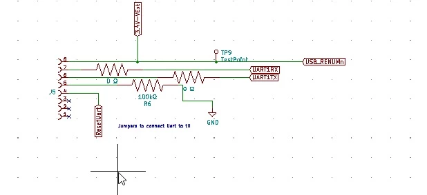
    The secondary signs-of-life methode2: Yes I did switches the BOOT0 pin to 3.3 Volts (see schematic label ResetUART). I measured the boot0 pin and its perfectly high if I place the jumper , if I remove the jumper it goes to zero volts for the SWDIO and SWD programming mode like in methode 1. So after downloading software and opening flash loader demonstrator , the responder does not connect on any bautrate or any parity mode, so I cant even connect it from the flash loader demonstrator. 0690X00000BvoCeQAJ.jpg0690X00000BvoCKQAZ.png

    0690X00000Bvo8rQAB.jpg

    Ozzys
    OzzysAuthor
    Associate
    January 9, 2020

    I bought an ECS-320-12-36-CKM-TR crystal oscilator , and provided it with 2x 2pF capacitors. I was thinking Maybe the osscilation is not working?

    Piranha
    Principal III
    January 9, 2020

    That part is just a crystal without oscillator circuit and 2 pF is almost definitely not enough for it. From popular values 18 pF could be the most appropriate one, or probably 15 pF. Read this:

    https://blog.adafruit.com/2012/01/24/choosing-the-right-crystal-and-caps-for-your-design/

    But the MCU starts with internal oscillator anyway, therefore it shouldn't matter at this point. Probably try 10k pull-down resistor for BOOT0 and disconnect 47k pull-up resistor from NRST like in AN4325 figure 9. Have you read that document? :)

    Tesla DeLorean
    Guru
    January 10, 2020

    Ok, so chip doesn't seem to be functioning. Pin 1 looks to be correctly orientated.

    Still most probably pins and/or power

    The crystal isn't important for the ST-LINK or USART methods.

    Check the state of the NRST pin, if it is always low, check the VDDA

    Tips, Buy me a coffee, or three.. PayPal Venmo (See Profile) Up vote any posts that you find helpful, it shows what's working..
    Ozzys
    OzzysAuthor
    Associate
    January 10, 2020

    @Piranha A type fault of me , I mean I put two 12 pF capacitors, and yes that right it has to start with the internal oscillator anyway. Yes I have put an 100k resistor from BOOT0 to GND and disconnected 47k pull-up resistor from NRST but it still does not work, i even have a switch to reset the uC my self but even this does not work. VDDA=3.3V like it should be and NRST pin is 3.3 V high. NRST does not go low when I try to program it, with the oscilloscope on the NRST pin, the scope showed me the status with trigger mode, I can tell clearly that the reset pin does not go low when I send the program the the microcontroller, only if I reset the pin my self with the switch.

    Ozzys
    OzzysAuthor
    Associate
    January 10, 2020

    @Community member​ VDDA status as shown on figure.

    0690X00000BvqzJQAR.jpg

    Piranha
    Principal III
    January 10, 2020

    > Yes I have put an 100k resistor from BOOT0 to GND

    I said 10k and that's what ST recommends.

    > NRST does not go low when I try to program it

    I thought you have connected it to the debugger's RST pin!?

    Ozzys
    OzzysAuthor
    Associate
    January 11, 2020

    >I said 10k and that's what ST recommends.

    After replacing the 100k with 10k it still does not work.

    >I thought you have connected it to the debugger's RST pin!?

    Yes indeed I did, but I also got a switch, I did this for the certainty that it works.