

Solved
CAN Communication issue with STM32F4
/* USER CODE BEGIN Header */
/**
 ******************************************************************************
 * @file can.c
 * @brief This file provides code for the configuration
 * of the CAN instances.
 ******************************************************************************
 * @attention
 *
 * Copyright (c) 2023 STMicroelectronics.
 * All rights reserved.
 *
 * This software is licensed under terms that can be found in the LICENSE file
 * in the root directory of this software component.
 * If no LICENSE file comes with this software, it is provided AS-IS.
 *
 ******************************************************************************
 */
/* USER CODE END Header */
/* Includes ------------------------------------------------------------------*/
#include "can.h"
#include "main.h"

#include "usart.h"

CAN_HandleTypeDef hcan2;

static CAN_TxHeaderTypeDef TxHeader;
static CAN_RxHeaderTypeDef RxHeader;
static uint8_t TxData[8];
static uint8_t RxData[8];
static uint32_t TxMailbox;

static char Print_buffer[200];

#define CAN_BAUD_250K 8 // Prescaler for 250 Kbits per second
#define CAN_BAUD_500K 4 // Prescaler for 500 Kbits per second


/* CAN2 init function */
void MX_CAN2_Init(void)
{
HAL_StatusTypeDef HAL_error;
CAN_FilterTypeDef sFilterConfig;

 /*##-1- Configure the CAN peripheral #######################################*/
hcan2.Instance = CAN2;
hcan2.Init.Prescaler = CAN_BAUD_250K;
hcan2.Init.Mode = CAN_MODE_LOOPBACK; //CAN_MODE_NORMAL;
hcan2.Init.SyncJumpWidth = CAN_SJW_1TQ;
hcan2.Init.TimeSeg1 = CAN_BS1_16TQ;
hcan2.Init.TimeSeg2 = CAN_BS2_8TQ;
hcan2.Init.TimeTriggeredMode = DISABLE;
hcan2.Init.AutoBusOff = DISABLE;
hcan2.Init.AutoWakeUp = ENABLE;
hcan2.Init.AutoRetransmission = ENABLE;
hcan2.Init.ReceiveFifoLocked = DISABLE;
hcan2.Init.TransmitFifoPriority = DISABLE;

 HAL_error = HAL_CAN_Init(&hcan2);

 if (HAL_error != HAL_OK)
 {
 Error_Handler(HAL_error);
 }

 /*##-2- Configure the CAN Filter ###########################################*/
 sFilterConfig.FilterBank = 0;
 sFilterConfig.FilterMode = CAN_FILTERMODE_IDMASK;
 sFilterConfig.FilterScale = CAN_FILTERSCALE_32BIT;
 sFilterConfig.FilterIdHigh = 0x0000;
 sFilterConfig.FilterIdLow = 0x0000;
 sFilterConfig.FilterMaskIdHigh = 0x0000;
 sFilterConfig.FilterMaskIdLow = 0x0000;
 sFilterConfig.FilterFIFOAssignment = CAN_RX_FIFO0;
 sFilterConfig.FilterActivation = ENABLE;
 sFilterConfig.SlaveStartFilterBank = 14;

 HAL_error = HAL_CAN_ConfigFilter(&hcan2, &sFilterConfig);

 if (HAL_error != HAL_OK)
 {
 Error_Handler(HAL_error);
 }

 /*##-3- Start the CAN peripheral ###########################################*/
 HAL_error = HAL_CAN_Start(&hcan2);

 if (HAL_error != HAL_OK)
 {
 Error_Handler(HAL_error);
 }

 /*##-4- Activate CAN RX notification #######################################*/
 HAL_error = HAL_CAN_ActivateNotification(&hcan2, CAN_IT_RX_FIFO0_MSG_PENDING);

 if (HAL_error != HAL_OK)
 {
 Error_Handler(HAL_error);
 }
}

void HAL_CAN_MspInit(CAN_HandleTypeDef* canHandle)
{

 GPIO_InitTypeDef GPIO_InitStruct = {0};
 if(canHandle->Instance==CAN2)
 {
 /* USER CODE BEGIN CAN2_MspInit 0 */

 /* USER CODE END CAN2_MspInit 0 */
 /* CAN2 clock enable */
 // __HAL_RCC_CAN1_CLK_ENABLE();
 __HAL_RCC_CAN2_CLK_ENABLE();

 __HAL_RCC_GPIOB_CLK_ENABLE();
 /**CAN2 GPIO Configuration
 PB12 ------> CAN2_RX
 PB13 ------> CAN2_TX
 */
 GPIO_InitStruct.Pin = GPIO_PIN_13;
 GPIO_InitStruct.Mode = GPIO_MODE_AF_PP;
 GPIO_InitStruct.Pull = GPIO_NOPULL;
 GPIO_InitStruct.Speed = GPIO_SPEED_FREQ_VERY_HIGH;
 GPIO_InitStruct.Alternate = GPIO_AF9_CAN2;
 HAL_GPIO_Init(GPIOB, &GPIO_InitStruct);

 GPIO_InitStruct.Pin = GPIO_PIN_12;
 GPIO_InitStruct.Mode = GPIO_MODE_AF_PP;
 GPIO_InitStruct.Pull = GPIO_PULLUP;
 GPIO_InitStruct.Speed = GPIO_SPEED_FREQ_VERY_HIGH;
 GPIO_InitStruct.Alternate = GPIO_AF9_CAN2;
 HAL_GPIO_Init(GPIOB, &GPIO_InitStruct);

 /* CAN2 interrupt Init */
 HAL_NVIC_SetPriority(CAN2_TX_IRQn, 5, 0);
 HAL_NVIC_EnableIRQ(CAN2_TX_IRQn);

 HAL_NVIC_SetPriority(CAN2_RX0_IRQn, 5, 0);

 //HAL_NVIC_EnableIRQ(CAN2_RX0_IRQn);

 HAL_NVIC_SetPriority(CAN2_RX1_IRQn, 5, 0);
 //HAL_NVIC_EnableIRQ(CAN2_RX1_IRQn);

 HAL_NVIC_SetPriority(CAN2_SCE_IRQn, 5, 0);
 HAL_NVIC_EnableIRQ(CAN2_SCE_IRQn);
 /* USER CODE BEGIN CAN2_MspInit 1 */

 /* USER CODE END CAN2_MspInit 1 */
 }
}

void HAL_CAN_MspDeInit(CAN_HandleTypeDef* canHandle)
{

 if(canHandle->Instance==CAN2)
 {
 /* USER CODE BEGIN CAN2_MspDeInit 0 */

 /* USER CODE END CAN2_MspDeInit 0 */
 /* Peripheral clock disable */
 __HAL_RCC_CAN1_CLK_DISABLE();
 __HAL_RCC_CAN2_CLK_DISABLE();

 /**CAN2 GPIO Configuration
 PB12 ------> CAN2_RX
 PB13 ------> CAN2_TX
 */
 HAL_GPIO_DeInit(GPIOB, GPIO_PIN_12|GPIO_PIN_13);

 /* CAN2 interrupt Deinit */
 HAL_NVIC_DisableIRQ(CAN2_TX_IRQn);
 HAL_NVIC_DisableIRQ(CAN2_RX0_IRQn);
 HAL_NVIC_DisableIRQ(CAN2_RX1_IRQn);
 HAL_NVIC_DisableIRQ(CAN2_SCE_IRQn);
 /* USER CODE BEGIN CAN2_MspDeInit 1 */

 /* USER CODE END CAN2_MspDeInit 1 */
 }
}


/**
 * @brief Rx Fifo 0 message pending callback
 * hcan: pointer to a CAN_HandleTypeDef structure that contains
 * the configuration information for the specified CAN.
 * @retval None
 */
void HAL_CAN_RxFifo0MsgPendingCallback(CAN_HandleTypeDef *hcan)
{
 HAL_GPIO_TogglePin(GPIOB, GPIO_PIN_0);

 /* Get RX message */
 if (HAL_CAN_GetRxMessage(hcan, CAN_RX_FIFO0, &RxHeader, RxData) != HAL_OK)
 {
sprintf(Print_buffer, "CAN Read Error!\r\n");
uart_print(Print_buffer);
 }
 else
 {
sprintf(Print_buffer, "StdID: 0x%lX, IDE: 0x%lX , ExtId: 0x%lX, FMI: 0x%lX, RTR: 0x%lX, DLC: 0x%lX, TS: 0x%lX \r\n", RxHeader.StdId, RxHeader.IDE, RxHeader.ExtId,
RxHeader.FilterMatchIndex, RxHeader.RTR, RxHeader.DLC, RxHeader.Timestamp);
uart_print(Print_buffer);

sprintf(Print_buffer, "Data: 0x%X,0x%X,0x%X,0x%X,0x%X,0x%X,0x%X,0x%X \r\n", RxData[0], RxData[1], RxData[2], RxData[3],
RxData[4], RxData[5], RxData[6], RxData[7]);
uart_print(Print_buffer);

 }
}

void ReportCAN_Status(void)
{
HAL_StatusTypeDef HAL_error;
CAN_HandleTypeDef *can_handle = &hcan2;

uint32_t interrupts = READ_REG(can_handle->Instance->IER);
 uint32_t msrflags = READ_REG(can_handle->Instance->MSR);
 uint32_t tsrflags = READ_REG(can_handle->Instance->TSR);
 uint32_t rf0rflags = READ_REG(can_handle->Instance->RF0R);
 uint32_t rf1rflags = READ_REG(can_handle->Instance->RF1R);
 uint32_t esrflags = READ_REG(can_handle->Instance->ESR);

sprintf(Print_buffer, "Interrupts: 0x%lX, msr flags: 0x%lX , tsr flags: 0x%lX, rf0r flags: 0x%lX, rf1r flags: 0x%lX, esr flags: 0x%lX \r\n",
interrupts, msrflags, tsrflags, rf0rflags, rf1rflags, esrflags);
uart_print(Print_buffer);

CLEAR_BIT(can_handle->Instance->MSR, CAN_MSR_WKUI);

interrupts = READ_REG(can_handle->Instance->IER);
msrflags = READ_REG(can_handle->Instance->MSR);
tsrflags = READ_REG(can_handle->Instance->TSR);
 rf0rflags = READ_REG(can_handle->Instance->RF0R);
rf1rflags = READ_REG(can_handle->Instance->RF1R);
esrflags = READ_REG(can_handle->Instance->ESR);

sprintf(Print_buffer, "Interrupts: 0x%lX,msr flags: 0x%lX,tsr flags: 0x%lX,rf0r flags: 0x%lX,rf1r flags: 0x%lX,esr flags: 0x%lX \r\n",
interrupts, msrflags, tsrflags, rf0rflags, rf1rflags, esrflags);
uart_print(Print_buffer);

}

void SendCAN_Message(void)
{
HAL_StatusTypeDef HAL_error;
CAN_HandleTypeDef *can_handle = &hcan2;

uint32_t interrupts = READ_REG(can_handle->Instance->IER);
 uint32_t msrflags = READ_REG(can_handle->Instance->MSR);
 uint32_t tsrflags = READ_REG(can_handle->Instance->TSR);
 uint32_t rf0rflags = READ_REG(can_handle->Instance->RF0R);
 uint32_t rf1rflags = READ_REG(can_handle->Instance->RF1R);
 uint32_t esrflags = READ_REG(can_handle->Instance->ESR);

 TxHeader.StdId = 0;
 TxHeader.ExtId = 0x01FF0060;
 TxHeader.RTR = CAN_RTR_DATA;
 TxHeader.IDE = CAN_ID_EXT;
 TxHeader.DLC = 8;
 TxHeader.TransmitGlobalTime = ENABLE;

 TxData[0] = 0x01;
 TxData[1] = 0x12;
 TxData[0] = 0x28;
 TxData[0] = 0x20;
 TxData[0] = 0x16;
 TxData[0] = 0x05;
 TxData[0] = 0x00;
 TxData[0] = 0x02;

 HAL_error = HAL_CAN_AddTxMessage(&hcan2, &TxHeader, TxData, &TxMailbox);

 if (HAL_error != HAL_OK)
 {
 Error_Handler(HAL_error);
 }
}
When I set the CAN Mode to LOOP BACK the transmission works fine.
Interrupts: 0x2, msr flags: 0xC08 , tsr flags: 0x1C000003, rf0r flags: 0x0, rf1r flags: 0x0, esr flags: 0x0
Interrupts: 0x2,msr flags: 0xC08,tsr flags: 0x1C000003,rf0r flags: 0x0,rf1r flags: 0x0,esr flags: 0x0
When I run the same code in Normal Mode The same transmit message fails.
hcan2.Init.Mode = CAN_MODE_NORMAL;
Interrupts: 0x2, msr flags: 0xC08 , tsr flags: 0x19000008, rf0r flags: 0x0, rf1r flags: 0x0, esr flags: 0xF80057
Interrupts: 0x2,msr flags: 0xC08,tsr flags: 0x19000008,rf0r flags: 0x0,rf1r flags: 0x0,esr flags: 0xF80057
I have to assume that my transceiver must be the problem.
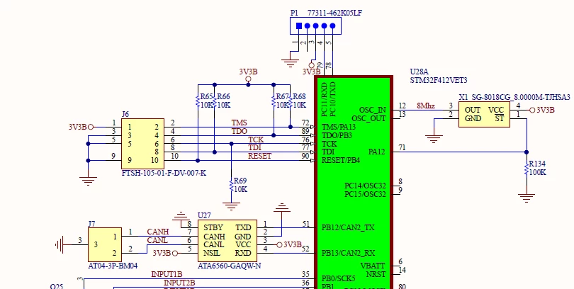
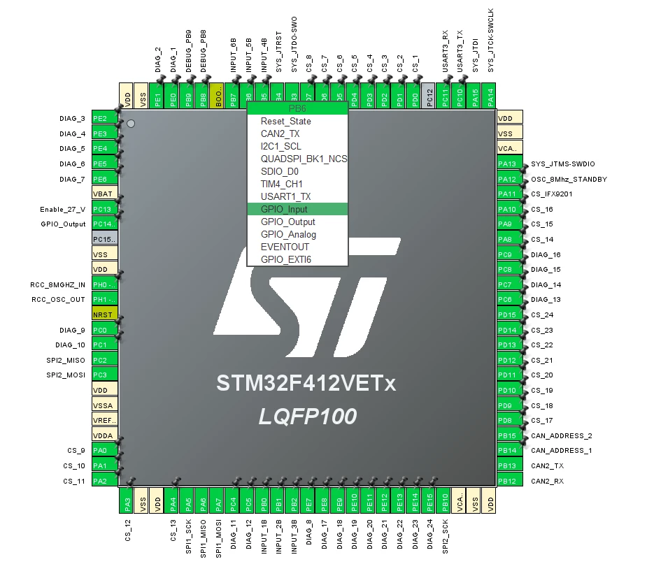
Can2 has another port pin but I think I selected the GPIO ports correctly.
void HAL_CAN_MspInit(CAN_HandleTypeDef* canHandle)
{
GPIO_InitTypeDef GPIO_InitStruct = {0};

if(canHandle->Instance==CAN2)
{
/* USER CODE BEGIN CAN2_MspInit 0 */

/* USER CODE END CAN2_MspInit 0 */
/* CAN2 clock enable */

// __HAL_RCC_CAN1_CLK_ENABLE();

__HAL_RCC_CAN2_CLK_ENABLE();

__HAL_RCC_GPIOB_CLK_ENABLE();

/**CAN2 GPIO Configuration
PB12 ------> CAN2_RX

PB13 ------> CAN2_TX

*/

GPIO_InitStruct.Pin = GPIO_PIN_13;
GPIO_InitStruct.Mode = GPIO_MODE_AF_PP;
GPIO_InitStruct.Pull = GPIO_NOPULL;
GPIO_InitStruct.Speed = GPIO_SPEED_FREQ_VERY_HIGH;
GPIO_InitStruct.Alternate = GPIO_AF9_CAN2;
HAL_GPIO_Init(GPIOB, &GPIO_InitStruct);


GPIO_InitStruct.Pin = GPIO_PIN_12;
GPIO_InitStruct.Mode = GPIO_MODE_AF_PP;
GPIO_InitStruct.Pull = GPIO_PULLUP;
GPIO_InitStruct.Speed = GPIO_SPEED_FREQ_VERY_HIGH;
GPIO_InitStruct.Alternate = GPIO_AF9_CAN2;
HAL_GPIO_Init(GPIOB, &GPIO_InitStruct);


/* CAN2 interrupt Init */

HAL_NVIC_SetPriority(CAN2_TX_IRQn, 5, 0);
HAL_NVIC_EnableIRQ(CAN2_TX_IRQn);
HAL_NVIC_SetPriority(CAN2_RX0_IRQn, 5, 0);

//HAL_NVIC_EnableIRQ(CAN2_RX0_IRQn);
HAL_NVIC_SetPriority(CAN2_RX1_IRQn, 5, 0);
//HAL_NVIC_EnableIRQ(CAN2_RX1_IRQn);

HAL_NVIC_SetPriority(CAN2_SCE_IRQn, 5, 0);
HAL_NVIC_EnableIRQ(CAN2_SCE_IRQn);

/* USER CODE BEGIN CAN2_MspInit 1 */

/* USER CODE END CAN2_MspInit 1 */
}