


CAN Communication: Baud Rate Configuration
Hello,
I have read the reference manual but the terminology used in the .ioc file and the reference manual do not align, so I am getting confused.
I am using the STM32H7B3I-EVAL evaluation board, which uses a STM32H7B3LIH6Q MCU. According to the datasheet, that has a clock frequency of 280 MHz. I am trying to configure the CAN protocol's baud rate and I need to determine what to set the parameters to. Specifically:
- NominalPrescaler/DataPrescaler
- NominalSyncJumpWidth/DataSyncJumpWidth
- NominalTimeSeg1/DataTimeSeg1
- NominalTimeSeg2/DataTimeSeg2
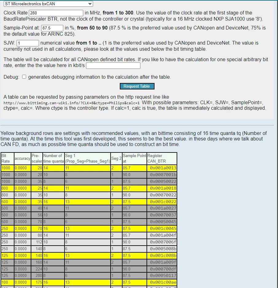
Based on what I've read online, I used this website to do my bit timing calculation:
http://www.bittiming.can-wiki.info/
I want to run a 500 kBit/s baud rate for my example. I would like to verify my steps:
Step 1: Determine FDCAN clock frequency
- For this, I went to the .ioc file and it says the FDCAN clock is 280 MHz (Proof: Picture FDCAN_Ex)
Step 2: Use bit timing calculation website:
Step 3: Define hfdcan1.Init parameters in code:

Based on this, have I configured this properly for 500 kBit/s? Do I have the nominal sync jump width used correctly? (I don't see a mention of sync jump width on the website).
If I have made any mistakes, I would appreciate some feedback! (Please note that I do not have an oscilloscope access at this moment, which is why I'm asking here first).