


Question
Am I correctly setting up TIM2 input capture?
Hi everyone.
I'm trying to setup TIM2_CH4 remapped as input capture, in order to detect rising edges on PB11.
I'm working with HALs. And my code is next:
First of all, for initialization:
 // APB2 (which is 64 MHz) at 8 MHz
 timer_cap_timhandle_.Instance = TIMx;
 timer_cap_timhandle_.Init.Period = 0;
 timer_cap_timhandle_.Init.Prescaler = 7;
 timer_cap_timhandle_.Init.ClockDivision = TIM_CLOCKDIVISION_DIV4;
 timer_cap_timhandle_.Init.CounterMode = TIM_COUNTERMODE_UP;
 timer_cap_timhandle_.Init.RepetitionCounter = 0;
 timer_cap_timhandle_.Init.AutoReloadPreload = TIM_AUTORELOAD_PRELOAD_DISABLE;

 // ---------------------------

 // Setup low level resources
 TIMx_CLK_ENABLE();

 //Interrupt priority
 HAL_NVIC_SetPriority(TIMx_IRQn, 0, 0);

 //Enable TIM2 interrupts
 HAL_NVIC_EnableIRQ(TIMx_IRQn);

 //Enable GPIOA timer
 __HAL_RCC_GPIOA_CLK_ENABLE();

 //Setup timer_cap and its handler
 if(HAL_TIM_IC_Init(&timer_cap_timhandle_) != HAL_OK)
 {
 //Error
 return -1;
 }

 //Remap I/O ports for TIM2
 __HAL_AFIO_REMAP_TIM2_ENABLE();

 //Variable setup
 memset (&timer_cap_mdata_, 0x00, sizeof (timer_cap_mdata_));
 timer_cap_ovf_callback_ = 0;
After that, I setup one channel (at this case, channel 4, i.e. idx = 3) by calling function set_callback:
int set_callback (uint8_t idx, timer_cap_mode_t config, time_callback_t timer_callback){

 //Previous check
 if (!(idx < TIMER_CALLBACK_NMAX)) return -1;

 //Callback refresh
 timer_cap_mdata_[idx].isr = timer_callback;

 //Starts callback overflow
 timer_cap_mdata_[idx].ovfs = 0;

 //If callback have assigned value, starts capture
 if (timer_cap_mdata_[idx].isr)
 {
 //Setting up capture mode
 configure_edge(idx, config);

 //Starts interrupt
 start_reference(idx);

 }
 else
 {
 //Stops interrupt
 timer_cap_stop_reference(idx);
 }

 return 0;

}


static int configure_edge (uint32_t idx, timer_cap_mode_t config)
{
 int channel;
 GPIO_TypeDef *gport;
 GPIO_InitTypeDef gstruct;


 if ((channel = timer_cap_idx2channel(idx)) < 0)
 {
 return -1;
 }


 switch (idx)
 {
 case 0:
 gport = GPIOA;
 gstruct.Pin = GPIO_PIN_15;
 break;
 case 1:
 gport = GPIOB;
 gstruct.Pin = GPIO_PIN_3;
 break;
 case 2:
 gport = GPIOB;
 gstruct.Pin = GPIO_PIN_10;
 break;
 case 3:
 gport = GPIOB;
 gstruct.Pin = GPIO_PIN_11;
 break;
 default:
 return -1;
 }

 //Setup PIN
 gstruct.Mode = GPIO_MODE_INPUT;
 gstruct.Pull = GPIO_NOPULL;
 HAL_GPIO_Init(gport, &gstruct);
 timer_cap_mdata_[idx].gport = *gport;
 timer_cap_mdata_[idx].gpin = gstruct.Pin;

 //Struct for input capture setup
 TIM_IC_InitTypeDef sICConfig;
 sICConfig.ICPolarity = 0;
 sICConfig.ICSelection = TIM_ICSELECTION_DIRECTTI;
 sICConfig.ICPrescaler = TIM_ICPSC_DIV1;
 sICConfig.ICFilter = 0;

 //Register the mode
 timer_cap_mdata_[idx].gmode = config;

 //Setup the edge
 if (config == TIMER_CAP_RISING)
 {
 sICConfig.ICPolarity = TIM_ICPOLARITY_RISING;
 }
 else if (config == TIMER_CAP_FALLING)
 {
 sICConfig.ICPolarity = TIM_ICPOLARITY_FALLING;
 }
 else if (config == TIMER_CAP_BOTH)
 {
 GPIO_PinState valueP = HAL_GPIO_ReadPin (&timer_cap_mdata_[idx].gport, timer_cap_mdata_[idx].gpin);

 if (valueP)
 {
 sICConfig.ICPolarity = TIM_ICPOLARITY_FALLING;
 }
 else
 {
 sICConfig.ICPolarity = TIM_ICPOLARITY_RISING;
 }
 }

 //Setup channel
 if(HAL_TIM_IC_ConfigChannel(&timer_cap_timhandle_, &sICConfig, channel) != HAL_OK)
 {
 return -1;
 }

 return 0;
}

static int start_reference (uint32_t idx)
{
 //Timer2 enable interrupt
 switch (idx){

 case 0:
 if(HAL_TIM_IC_Start_IT(&timer_cap_timhandle_, TIM_CHANNEL_1) != HAL_OK)
 return -1;
 break;
 case 1:
 if(HAL_TIM_IC_Start_IT(&timer_cap_timhandle_, TIM_CHANNEL_2) != HAL_OK)
 return -1;
 break;
 case 2:
 if(HAL_TIM_IC_Start_IT(&timer_cap_timhandle_, TIM_CHANNEL_3) != HAL_OK)
 return -1;
 break;
 case 3:
 if(HAL_TIM_IC_Start_IT(&timer_cap_timhandle_, TIM_CHANNEL_4) != HAL_OK)
 return -1;
 break;
 default:
 return -1;
 }

 return 0;
}
Why I am not having any interrupt? My registers value after set_callback function is next:
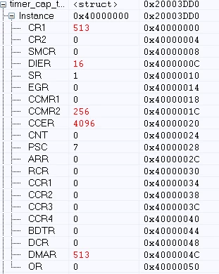
Which seems to be OK. So, what's the matter? Why I'm not getting any interrupt?
I'm using STM32105VC microcontroller.
Thank you in advance!
