

Ngyuen1980
Associate
September 28, 2019
Solved

ADC and timer(s): Measuring moving average peak voltage of PWM signal with varying amplitude

  • September 28, 2019
  • 6 replies
  • 4018 views

I want to measure a moving average of the amplitude of a fix frequency, fixed dutycyle PWM signal with slowly varying amplitude but in a noisy environment (DC motors).

I want to use as little as possible CPU power to do this and have the ADC do this for me. I have an internal signal coming from a timer that is in sync with the signal to measure. I can use this as a trigger.

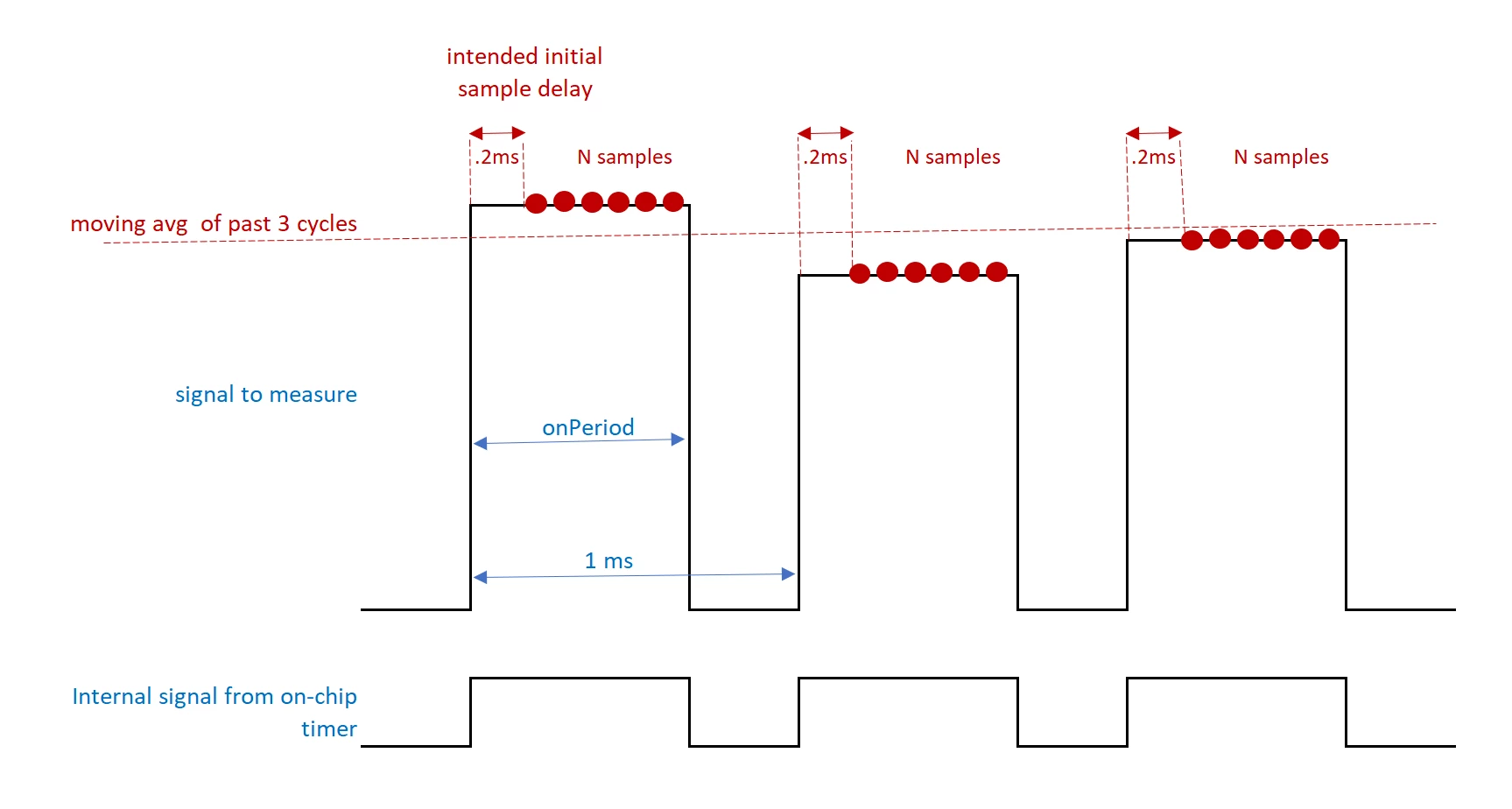
Below is what I try to do:
0690X000009jnqRQAQ.png

  1. use the internal trigger from the timer on the chip that actually generates the PWM signal
  2. wait 1/4th of the onPeriod before taking any samples to filter out rising time or overshoot
  3. then take N samples and filter out noise by taking the arithmetic average
  4. keep a constant moving average of the M past cycles (3 in the drawing, 100 in reality)
  5. Store this result in an ADC register such that the application can always retrieve the last 100ms average

So far, I figured out 1 (interconnect of timer output channel and ADC external trigger) and 3 (oversampling) by reading the reference manual and think I can do 2 by using a basic timer inbetween first timer output and ADC. But I completely struggle with 4 and 5.

Can this be done? I am using STM32L4 and F4/7.

This topic has been closed for replies.
Best answer by S.Ma

From the same timer generating the internal signal, I will use another compare channel fed with a cyclic dma fed ROM Table. This will create a burst of pulses triggering the conversion of the ADC whenever it is needed within the internal signal period. The precision in timings depends on the timer clock frequency.

Then use a DMA to cyclic feed a SRAM table from ADC spit out data and get notified to process the previous 1/2 batch from the buffer.

This would relax the interrupt latency quite a lot, isn't it?

6 replies

waclawek.jan
Super User
September 28, 2019

For 4. you need to use the processor to calculate the average.

For 5., why would it need to be an ADC register, why can't it be simply a variable in memory?

JW

Ngyuen1980
Associate
September 29, 2019

4: I could see that. But maybe there is some DSP functionality in some of the chips?

5: since when posting I had not looked into DMA yet.

S.Ma
S.MaBest answer
Principal
September 28, 2019

From the same timer generating the internal signal, I will use another compare channel fed with a cyclic dma fed ROM Table. This will create a burst of pulses triggering the conversion of the ADC whenever it is needed within the internal signal period. The precision in timings depends on the timer clock frequency.

Then use a DMA to cyclic feed a SRAM table from ADC spit out data and get notified to process the previous 1/2 batch from the buffer.

This would relax the interrupt latency quite a lot, isn't it?

Ngyuen1980
Associate
September 29, 2019

Thank you. I understand the idea of the circular DMA buffer now. I would still like to go with oversampling within the internal signal period. Writing more than one value per cycle to DMA register does not seem efficient if oversampling can do the averaging in the ADC

S.Ma
Principal
September 28, 2019

And maybe (didn't check it out) some STM32L4 can have the digital filter DFSDM fed by ADC which might also help reduce processing time.

Ngyuen1980
Associate
October 1, 2019

HD13139 answers it for me! many thanks. I will go the DMA route