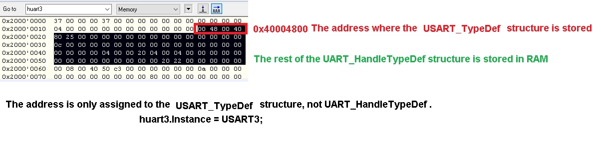
7 USART3 registers == 28 bytes. What are the other addresses in USART3 for?
STM32F407 Discovery
typedef struct __UART_HandleTypeDef
{
USART_TypeDef *Instance;
UART_InitTypeDef Init;
const uint8_t *pTxBuffPtr;
uint16_t TxXferSize;
__IO uint16_t TxXferCount;
uint8_t *pRxBuffPtr;
uint16_t RxXferSize;
__IO uint16_t RxXferCount;
__IO HAL_UART_RxTypeTypeDef ReceptionType;
DMA_HandleTypeDef *hdmatx;
DMA_HandleTypeDef *hdmarx;
HAL_LockTypeDef Lock;
__IO HAL_UART_StateTypeDef gState;
__IO HAL_UART_StateTypeDef RxState;
__IO uint32_t ErrorCode;
} UART_HandleTypeDef;
I take the USART3 setting as an example.
The starting address for storing this UART_HandleTypeDef structure will be 0x4000 4800.
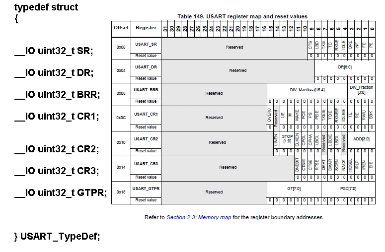
USART3 has 7 registers. Each register is 32 bits.
7*32==224/8==28 bytes
7 USART3 registers occupy 28 bytes.
These 7 registers are configured by the USART_TypeDef *Instance structure;
0x4000 4800 + 28 bytes== 4000 481C
0x4000 4800 ----- 4000 481C There are 7 registers in this address limit.
But USART3 is allocated a lot more addresses 0x4000 4800 - 0x4000 4BFF What's in there?
And most importantly, I'm wondering where it is stored:
UART_InitTypeDef Init;
const uint8_t *pTxBuffPtr;
uint16_t TxXferSize;
__IO uint16_t TxXferCount;
uint8_t *pRxBuffPtr;
uint16_t RxXferSize;
__IO uint16_t RxXferCount;
__IO HAL_UART_RxTypeTypeDef ReceptionType;
DMA_HandleTypeDef *hdmatx;
DMA_HandleTypeDef *hdmarx;
HAL_LockTypeDef Lock;
__IO HAL_UART_StateTypeDef gState;
__IO HAL_UART_StateTypeDef RxState;
__IO uint32_t ErrorCode;
And what does it set up? Or they are ordinary variables and are stored as ordinary data, while registers are not configured.
That is, there are only 7 registers in this address limit 0x4000 4800 - 0x4000 4BFF, right?
What is the rest of the space for?