


addebito
Associate
September 22, 2020
Question

NUCLEO-F401RE and a X-NUCLEO-IHM03A1

  • September 22, 2020
  • 12 replies
  • 2765 views

Hi at all,

I bought a NUCLEO-F401RE and a X-NUCLEO-IHM03A1.

I've created a STM32CubeIDE project starting from the example "IHM03A1_ExampleFor1Motor" included inside the "STM32CubeExpansion_SPN3_V1.6.0" package.

I downloaded the project on Nucleo F401RE board and everything works fine.

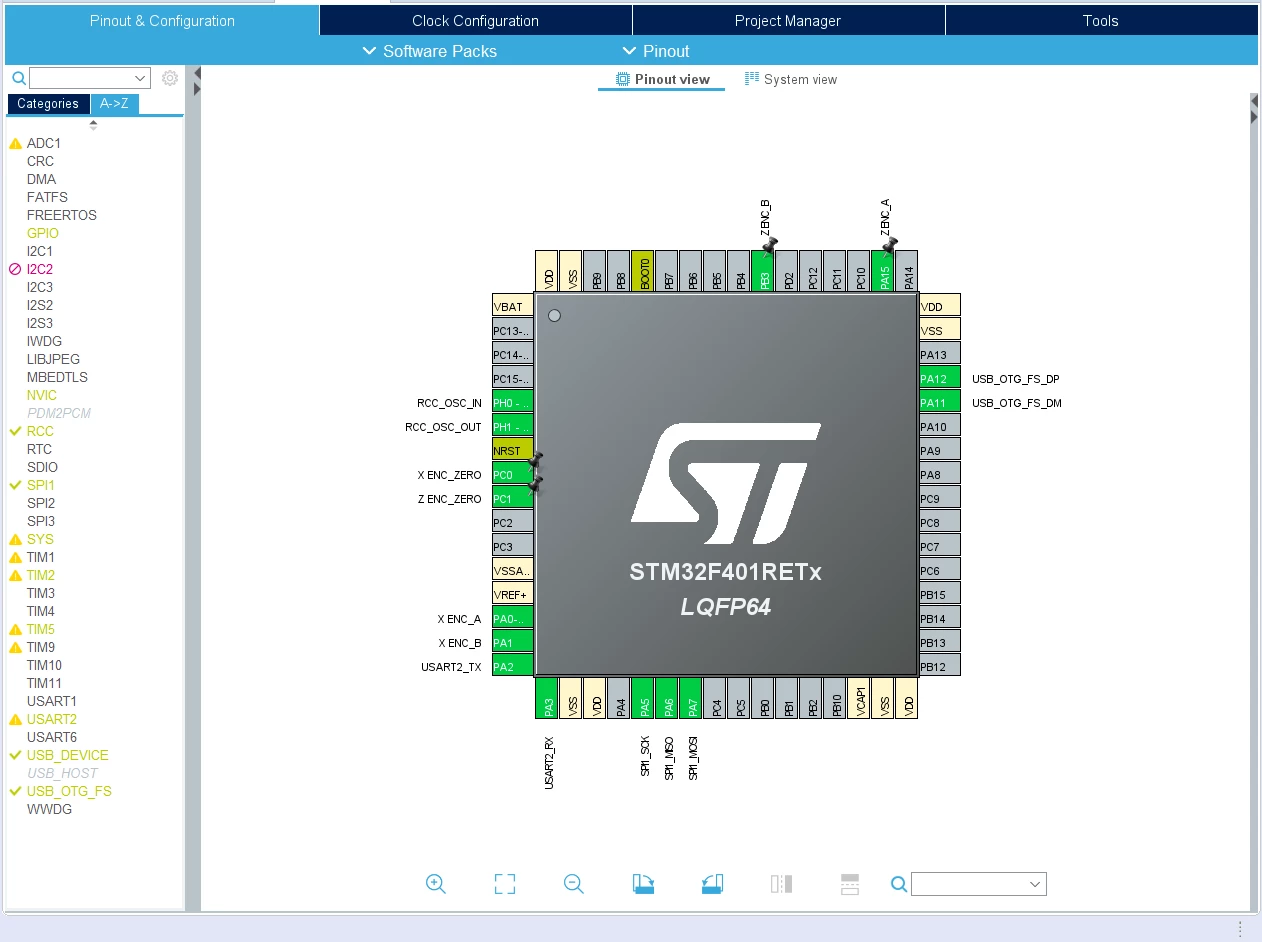
Now I'm trying to integrate this motor example on my project that manage:

- TIM2 32 bit counter (external encoder 1)

- TIM5 32 bit counter (external encoder 2)

- 2 external interrrupt (encoders index to reset the counter values)

- USB OTG used to communicate with a computer as virtual com port

But when I download this new project the firmware hang when I call

BSP_MotorControl_Init(BSP_MOTOR_CONTROL_BOARD_ID_POWERSTEP01, NULL);

Obviusly my project without the motor section works fine.

I think there are some mismatch between the the sample motor project and my project configurations.

Eg:

this is the clock config of the motor sample project

void SystemClock_Config(void)
{
 RCC_ClkInitTypeDef RCC_ClkInitStruct;
 RCC_OscInitTypeDef RCC_OscInitStruct;
 
 /* Enable Power Control clock */
 __PWR_CLK_ENABLE();
 
 /* The voltage scaling allows optimizing the power consumption when the device is 
 clocked below the maximum system frequency, to update the voltage scaling value 
 regarding system frequency refer to product datasheet. */
 __HAL_PWR_VOLTAGESCALING_CONFIG(PWR_REGULATOR_VOLTAGE_SCALE2);
 
 /* Enable HSE Oscillator and activate PLL with HSI as source */
 RCC_OscInitStruct.OscillatorType = RCC_OSCILLATORTYPE_HSI;
 RCC_OscInitStruct.HSIState = RCC_HSI_ON;
 RCC_OscInitStruct.HSICalibrationValue = 16;
 RCC_OscInitStruct.PLL.PLLState = RCC_PLL_ON;
 RCC_OscInitStruct.PLL.PLLSource = RCC_PLLSOURCE_HSI;
 RCC_OscInitStruct.PLL.PLLM = 16;
 RCC_OscInitStruct.PLL.PLLN = 336;
 RCC_OscInitStruct.PLL.PLLP = RCC_PLLP_DIV4;
 RCC_OscInitStruct.PLL.PLLQ = 7;
 if(HAL_RCC_OscConfig(&RCC_OscInitStruct) != HAL_OK)
 {
 MyErrorHandler(0);
 }
 
 /* Select PLL as system clock source and configure the HCLK, PCLK1 and PCLK2 
 clocks dividers */
 RCC_ClkInitStruct.ClockType = (RCC_CLOCKTYPE_SYSCLK | RCC_CLOCKTYPE_HCLK | RCC_CLOCKTYPE_PCLK1 | RCC_CLOCKTYPE_PCLK2);
 RCC_ClkInitStruct.SYSCLKSource = RCC_SYSCLKSOURCE_PLLCLK;
 RCC_ClkInitStruct.AHBCLKDivider = RCC_SYSCLK_DIV1;
 RCC_ClkInitStruct.APB1CLKDivider = RCC_HCLK_DIV2; 
 RCC_ClkInitStruct.APB2CLKDivider = RCC_HCLK_DIV1; 
 if(HAL_RCC_ClockConfig(&RCC_ClkInitStruct, FLASH_LATENCY_2) != HAL_OK)
 {
 MyErrorHandler(1);
 }
}

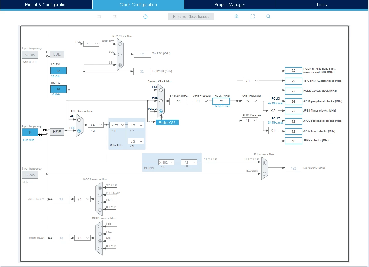
This is my clock config auto generated by STM32CubeIDE

void SystemClock_Config(void)
{
 RCC_OscInitTypeDef RCC_OscInitStruct = {0};
 RCC_ClkInitTypeDef RCC_ClkInitStruct = {0};
 
 /** Configure the main internal regulator output voltage
 */
 __HAL_RCC_PWR_CLK_ENABLE();
 __HAL_PWR_VOLTAGESCALING_CONFIG(PWR_REGULATOR_VOLTAGE_SCALE2);
 /** Initializes the RCC Oscillators according to the specified parameters
 * in the RCC_OscInitTypeDef structure.
 */
 RCC_OscInitStruct.OscillatorType = RCC_OSCILLATORTYPE_HSE;
 RCC_OscInitStruct.HSEState = RCC_HSE_ON;
 RCC_OscInitStruct.PLL.PLLState = RCC_PLL_ON;
 RCC_OscInitStruct.PLL.PLLSource = RCC_PLLSOURCE_HSE;
 RCC_OscInitStruct.PLL.PLLM = 4;
 RCC_OscInitStruct.PLL.PLLN = 72;
 RCC_OscInitStruct.PLL.PLLP = RCC_PLLP_DIV2;
 RCC_OscInitStruct.PLL.PLLQ = 3;
 if (HAL_RCC_OscConfig(&RCC_OscInitStruct) != HAL_OK)
 {
 Error_Handler();
 }
 /** Initializes the CPU, AHB and APB buses clocks
 */
 RCC_ClkInitStruct.ClockType = RCC_CLOCKTYPE_HCLK|RCC_CLOCKTYPE_SYSCLK
 |RCC_CLOCKTYPE_PCLK1|RCC_CLOCKTYPE_PCLK2;
 RCC_ClkInitStruct.SYSCLKSource = RCC_SYSCLKSOURCE_PLLCLK;
 RCC_ClkInitStruct.AHBCLKDivider = RCC_SYSCLK_DIV1;
 RCC_ClkInitStruct.APB1CLKDivider = RCC_HCLK_DIV2;
 RCC_ClkInitStruct.APB2CLKDivider = RCC_HCLK_DIV1;
 
 if (HAL_RCC_ClockConfig(&RCC_ClkInitStruct, FLASH_LATENCY_2) != HAL_OK)
 {
 Error_Handler();
 }
}
0693W000004GmCSQA0.png

0693W000004GmDBQA0.png

I've also welded a XTAL 8 Mz + 2 capacitors on my NUCLEO F401RE and cut off the ST-Link debugger.

Any suggestions will be greatly appreciated.

Thank you so much.

This topic has been closed for replies.

12 replies

Laurent Ca...
Senior III
September 23, 2020

Dear @addebito​ 

What is the MC-SDK version number you use?

Best regards

Laurent Ca...

addebito
addebitoAuthor
Associate
September 28, 2020

@Laurent Ca...​  do you have any suggestions?

If there's someone else that has an idea to understand how to check / verify the problem... please let me know.

Thank you.

Best regards.

addebito
addebitoAuthor
Associate
September 23, 2020

Dear Laurent,

thank you for your reply.

I've download the "en.x-cube-spn3.zip" at this link:

https://www.st.com/en/embedded-software/x-cube-spn3.html#overview

No MC-SDK but I've created a project by "STM32CubeIDE 1.3.0" starting from the single motor example application contained inside the zip file

.\STM32CubeExpansion_SPN3_V1.6.0\Projects\Multi\Examples\MotionControl\IHM03A1_ExampleFor1Motor

Best regards.

Laurent Ca...
Senior III
September 29, 2020

Dear @addebito​ 

Could you give us more details about the motor(s) you use?

Best regards

Laurent C...

addebito
addebitoAuthor
Associate
September 29, 2020

Dear @Laurent Ca...​ ,

follow the motor specification but IMHO I don't think it could be a motor problem because when I download and run the example "IHM03A1_ExampleFor1Motor" included inside the "STM32CubeExpansion_SPN3_V1.6.0" package, everything works fine.

I see the motor movements as described through the comments inside the source code.

The problem appear when I merge the 2 projects.

  • My project to read some counters and com port to communicate to a computer
  • Example project "IHM03A1_ExampleFor1Motor"

Anyway, this is the motor specifications

Step Angle: 1.8°

Step Angle Accuracy: ±5% (full step, no load)

Resistance Accuracy: ±10%

Inductance Accuracy: ±20%

Temperature Rise: 80 °C Max.(rated current, 2 phase on)

Ambient Temperature: �?20 °C ~ +50 °C

Insulation Resistance: 100 MΩ Min., 500VDC

Dielectric Strength: 500 VAC for one minute

Shaft Radial Play: 0.02 Max. (450 g�?load)

Shaft Axial Play: 0.08 Max. (450 g�?load)

Current (A/Ø): 4.2

Resistance (Ω/Ø): 0.8

Inductance (mH/Ø): 3.0

HoldingTorque (N.cm): 300

DetentTorque (N.cm): 12.0

RotorInertia (g.cm2): 780

Bi/Unipolar (# of Leads): Bi (4)

Weight (g): 1600

Length (mm): 90

Laurent Ca...
Senior III
October 15, 2020

Dear @addebito​ 

I am in the team working on the MC SDK and have no idea to the content of "STM32CubeExpansion_SPN3_V1.6.0" package.

Sorry to not be able to help you more.

Is there someone in the STM32 Community able to help @addebito​ on this problem?

Thanks by advance.

Best regards

Laurent Ca...

Tesla DeLorean
Guru
October 15, 2020

The motor users in my experience are not heavy forum participants.

If there are issues with the clocks you need to make sure they are starting properly, and not going into Error_Handler()

Zeroing the local/auto variables is strongly suggested as they will otherwise contain random junk.

Cutting of the ST-LINK is going to make debugging more difficult. You really need to inspect the state of the MCU and peripherals to see exact where it has stopped, if it has actually crashed or faulted, or is simply waiting for a response from a peripheral that's not being clocked, etc.

At a minimum I would recommend instrumenting Error_Handler() and HardFault_Handler() with output of actionable data to a serial port.

Tips, Buy me a coffee, or three.. PayPal Venmo (See Profile) Up vote any posts that you find helpful, it shows what's working..
chaaalyy
Senior II
October 15, 2020

I think, this is just a problem of conflicting Pins.... I don´t know much about the used Nucleo-Board (esp. the pinout...), but that´s, where i would begin to search. There are just a few possibilities: first wrong SPI-settings (SPI is used to communicate with the expansion board) and second: forget about the step-signal pin (not used in examples) and maybe also about "busy" and/or "flag". For these two pins: just delete the according initialization code and especially the Interrupts ! The Flag Interrupt is fired at startup and there´s a high chance of being the cause for the crash. Give it a try and if your project works... you´re on the right way ;)

/Charly

P.S.: check the pinout settings in the ihm03a1 example: You need SPI-pins, correct SPI-setup (parameters) and maybe (if still available in your hardware) flag and busy - pins correctly configured. Leave the rest (clock settings and so on) untouched in your project. Then merge just the libraries, example code from mainloop and errorhandler (also in main.c of example), as well, as according interrupt handlers from stm32f4xx_it.c

addebito
addebitoAuthor
Associate
October 25, 2020

Thank you all for your kind reply.

I have resolved.

I forgot some configurations inside these init functions.

void HAL_SPI_MspInit(SPI_HandleTypeDef* hspi)
{
...
}
 
void HAL_TIM_PWM_MspInit(TIM_HandleTypeDef* htim_pwm)
{
...
}

addebito
addebitoAuthor
Associate
October 27, 2020

Hi @Laurent Ca...​ , I've tasting victory too early....

I've done some test with some commands and the stepper motor works fine but I've another problem that I didn't have before.

Through the computer by the USB Virtual Com Port I send some ascii command to the STM32, but now I can't open the com port on my OS.

Yes, I get an error (10) when I try to open the com port.

This is the QT case error (10 = ERROR_INVALID_PARAMETER).

 case ERROR_INVALID_PARAMETER:
 error.errorCode = QSerialPort::UnsupportedOperationError;
 break;

I've done some test to investigate, follow some informations:

OS: Windows 10

Framework: QT 5.14.2 with QSerialPort class to communicate

STM32: PA11, PA12 (you can see on my first picture in the first post)

Board: NUCLEO-STM32F401RE and X-NUCLEO-IHM03A1

I know, seems like a QT problem, but if I download the old firmware, without all the motor section / initializations the communication works fine !!

if it helps, I can send you the 2 STM32 projects:

  • 1st the USB communication works but without motor
  • 2nd the USB communication doesn't work but with motor

Thank you for your support.

addebito
addebitoAuthor
Associate
October 28, 2020

Hi @Laurent Ca...​ , @Karl Hönemann​ , @Community member​ ,

I've done the follow steps.

1) Update the fw package to the last one 1.25.1 inside the ProjectManager0693W0000059YUrQAM.pngTry again but I've the same error

2) Apply the patch called "en.patch_cubef4.zip"

Try again but I've the same error

3) Added these lines of code into the "CDC_Control_FS" function inside the "usbd_cdc_if.c" (thanks google).

 case CDC_GET_LINE_CODING:
 	if (length == 7)
 	{
 		uint32_t bitrate = 9600;
 
 		pbuf[0] = (uint8_t)(bitrate);
 		pbuf[1] = (uint8_t)(bitrate >> 8);
 		pbuf[2] = (uint8_t)(bitrate >> 16);
 		pbuf[3] = (uint8_t)(bitrate >> 24);
 		pbuf[4] = 0; // 1 stop bit
 		pbuf[5] = 0; // parity none
 		pbuf[6] = 8; // datatype
 	}
 break;

Try again and now it's working !!

I'd like to ask you, in your opinion this is the correct way or is a band-aid solution?

Do you have any other suggestions?

Thank you for your support & your time.