luke514
Associate III
June 9, 2026
Solved

Motor with encoder and FOC spinning poorly and roughly at low speed

  • June 9, 2026
  • 5 replies
  • 136 views

Hi everyone, I’m using the X-NUCLEO-IHM08M1 with the g474re core and a BL23E33-01D-04RO motor (which reaches 4000 rpm).

I want to use FOC and the motor’s internal encoder, so I’ve made the hardware modifications described in the IHM08M1 manual and those also required by MC Workbench before code generation. I have therefore set the main sensor to the encoder and the auxiliary sensor to the sensorless PLL+observer.

In STM32CubeIDE, the motor runs smoothly and the speed is correct, but at low speeds (below 60 rpm) it freezes and sometimes lags... I have no reported firmware errors. I don't have any load connected to the motor (yet).

What could be causing this? PID?


I can provide screenshots of the signals you want; I’m using CubeMonitor.
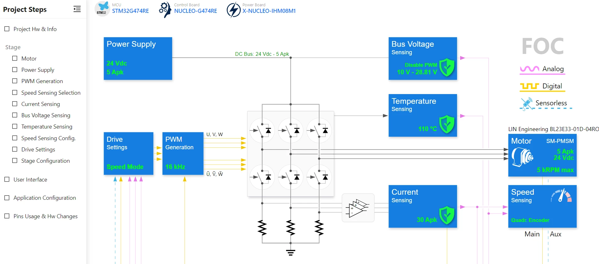
 

PWM: 16kHz

SW dead time 850ns

Regulator execution time: 63us (1 PWM) - three shunt

Gain: 5.18

Bus voltage divider: 19.17

Quadrature encoder:

  • average FIFO depth = 16
  • Input capture filter duration = 0.75 us

PID: autocalculate Kp & Ki for both current and speed regulator


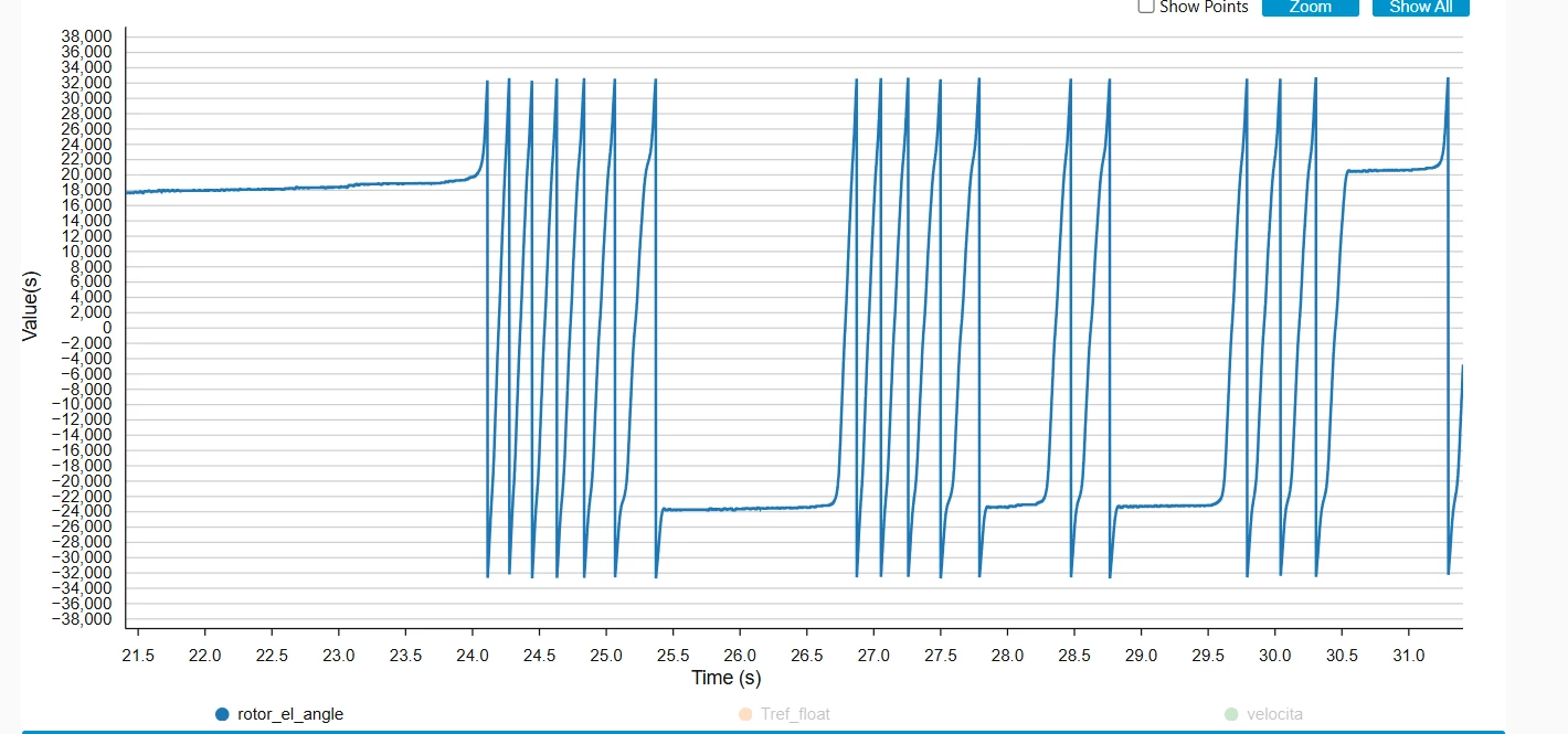
-------------------------------------30 rpm - motor not spinning or spinning poorly/roughly----------------------------------------------------------


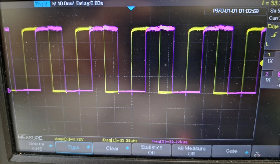
Encoder from oscilloscope:
https://streamable.com/2xdrsx

(If the link expires, let me know and I'll update it)


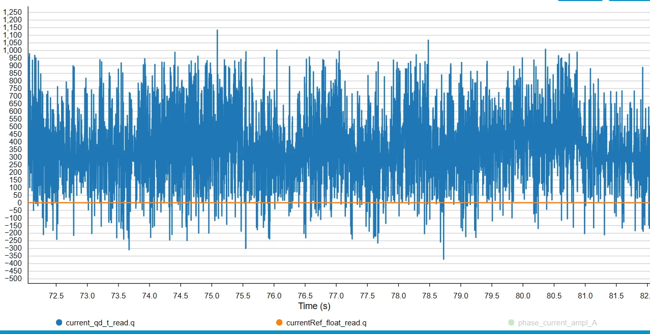
-----------------------------------------------------------------2000 rpm--------------------------------------------

 

Best answer by Peter BENSCH

This behaviour is normal in FOC drives at very low speed. Below a certain rpm, the available feedback and the motor’s back-EMF become very small, so friction, cogging torque, measurement resolution and controller tuning have a much stronger impact.

So it is not necessarily a firmware fault or only a PID issue. The low-speed instability comes mostly from a combination of speed-loop tuning, encoder speed quantisation, and the limitations of sensorless estimation at low speed.

However, in 2023 STMicroelectronics developed the proprietary method called ZeST, which makes it possible to achieve full torque at very low speeds (Zero Speed Full Torque). It is available to selected customers with sufficiently large projects:

Hope that helps?

Regards
/Peter

5 replies

Peter BENSCH
Peter BENSCHBest answer
ST Technical Moderator
June 9, 2026

This behaviour is normal in FOC drives at very low speed. Below a certain rpm, the available feedback and the motor’s back-EMF become very small, so friction, cogging torque, measurement resolution and controller tuning have a much stronger impact.

So it is not necessarily a firmware fault or only a PID issue. The low-speed instability comes mostly from a combination of speed-loop tuning, encoder speed quantisation, and the limitations of sensorless estimation at low speed.

However, in 2023 STMicroelectronics developed the proprietary method called ZeST, which makes it possible to achieve full torque at very low speeds (Zero Speed Full Torque). It is available to selected customers with sufficiently large projects:

Hope that helps?

Regards
/Peter

In order to give better visibility on the answered topics, please click on Accept as Solution on the reply which solved your issue or answered your question.
luke514
luke514Author
Associate III
June 9, 2026

Hi again and thank you for your detailed reply.

I have two more questions:

  1. My primary sensor is the encoder, but I’m not quite sure what ‘auxiliary sensor’ means (i.e. PLL + observer). Does it mean that it only “activates” when the encoder fails? Or does it mean that it always runs in the “background” but the angle is estimated solely by the primary encoder? Or, yet another option, that the angle used in FOC is an average of the two (encoder + auxiliary observer)?
     
  2. This question is actually linked to the first one; it’s very similar. You said that the low-speed instability comes mostly from a combination of speed-loop tuning, encoder speed quantisation, and the limitations of sensorless estimation at low speed. Can I rule out this last cause – “limitations of sensorless estimation at low speed” – given that the primary sensor I have set up is the encoder?


Unfortunately, due to the specifications of my application, I have to use the encoder; I can’t rely on sensorless mode… so I can’t switch to sensorless mode at low speeds and use the encoder at high speeds. So I’ll find a way to sort it out.

  1. When you write “encoder speed quantisation”, what do you mean? Do you mean a software-related issue (FIFO registers, etc.) or a hardware issue, perhaps due to the type of encoder, its specifications, etc.?
Peter BENSCH
ST Technical Moderator
June 9, 2026

Regarding the first question, I cannot make any statement.

If the encoder is truly the primary feedback sensor in closed-loop operation, then the low-speed limitations of the sensorless observer are unlikely to be the main cause. The more probable causes are as mentioned speed-loop tuning, encoder speed quantisation/filtering, and additionally mechanical effects such as friction and cogging torque. The sensorless observer could still have an indirect effect if it is used in startup, fallback, or validation logic, so it is worth checking that the system is not switching over or relying on it in the low-speed region.

Encoder speed quantisation means: the encoder measures position very well, but the velocity derivative is often noisy or coarsely quantised during very slow movement, especially when the evaluation is heavily filtered.

Regards
/Peter

In order to give better visibility on the answered topics, please click on Accept as Solution on the reply which solved your issue or answered your question.
GMA
ST Technical Moderator
June 11, 2026

Hello ​@luke514,

The auxiliary speed sensor indicates that the associated algorithm is active, but the result is not used to control the motor.
The motor control can switch between the primary and auxiliary speed sensors by using the MC Pilot Switch Sensor feature or the MC_SensorSwitchMotor1() application programming interface (API).

The SPEED proportional-integral (PI) regulator parameters can be adjusted with the MC Motor Pilot tool: Advanced Configuration, use Speed PI regulator parameters.

If you agree with the answer, please accept it by clicking on 'Best answer'.Best regards.GMA
luke514
luke514Author
Associate III
June 11, 2026

Hi, and thank you for your reply.

So you’re suggesting I use Motor Pilot to quickly test the PI parameters and, once I’ve found the right ones, update them in MC Workbench:


Would you recommend I experiment with Flux/Torque Kp and Ki first?