
Senior III
May 26, 2025
Question

Motor current waveforms custom board + MCSDK

  • May 26, 2025
  • 3 replies
  • 860 views

I am trying to run a custom board using MCSDK micro STM32G4 series,  using cube monitor took the waveforms i have queries on the waveforms pls help me if they are correct or abnormal
STuser2_0-1748261559749.png

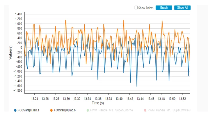
a. Phase currents are not correct, i am not sure why are not overlapping, i mean 120 phase shifted.

b. 
STuser2_1-1748261707737.png

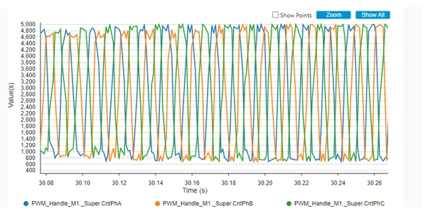
CntPhA, CntPhB, CntPhC look to be ok for me but the problem i am observing is the duty cycle is going upto 5000 i have set the system at 15Khz hence the max count is 5666, does it mean it already got saturated, i am running the motor at 26V the motor is run at 60V in the vehicle.

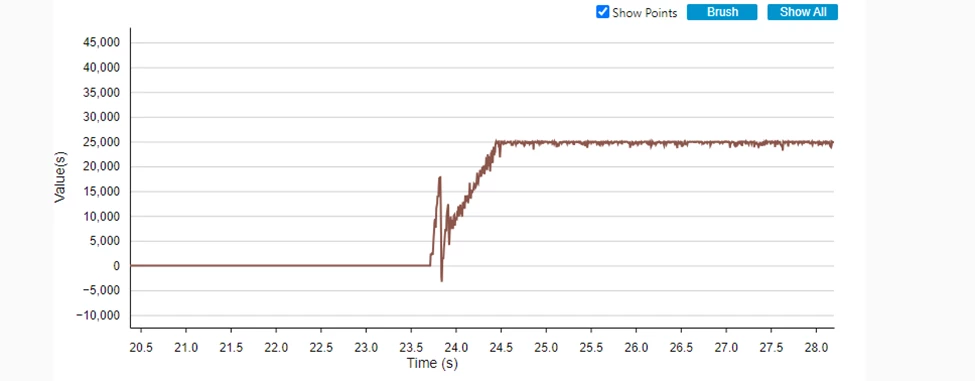
Vq graph 
STuser2_2-1748261979650.png

c. Vq also going upto 25000.

d. 

/*** Noise parameters ***/

#define TNOISE_NS 500

#define TRISE_NS 200

i have never measured the above values on the scope including the Dead Time for my system,

is it mandatory to measure the above values and input to the system.

This topic has been closed for replies.

3 replies

GMA
ST Technical Moderator
May 28, 2025

Hello @STuser2,

Phase current signals are available on STMC Motor pilot. 

GMA_0-1748444741718.png


If you agree with the answer, please accept it by clicking on 'Best answer'.Best regards.GMA
STuser2Author
Senior III
May 30, 2025

Thank you for reply, i have added a hardware filter with cut off at 110KHz and performing PWM switching frequency of 15Khz. My understanding is Phase A and noise on Phase B current waveforms are different even i use the same filter. The problem is at 40V after few seconds the over voltage protection fault is triggered, and the motor is stopped. I don't know how do i debug it. Any suggestions before i change the filter again to around cut off 230KHz. 


STuser2_0-1748577826783.png

STuser2_1-1748577862025.png

STuser2_2-1748578017059.png


STuser2Author
Senior III
May 30, 2025

One other observation is when i run the system in open loop at very low RPM and i plot in cube monitor Ia, Ib currents 

STuser2_0-1748584632924.png

The Ib current is having an offset i tested in 2 different boards with different filter capacitors, any mistake in the software that i have done?

Just a doubt is Ia proper or Ib proper waveform?

STuser2_0-1748590214377.png

Iapha and IBeta waveforms in open loop. I have doubt on Ialpha which shall be sinusoidal.