Visitor
October 15, 2026
Question

MCSDK 6.4.1: ESC PWM input configured on PB10 but generated on PA15

Hello ST team,

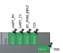
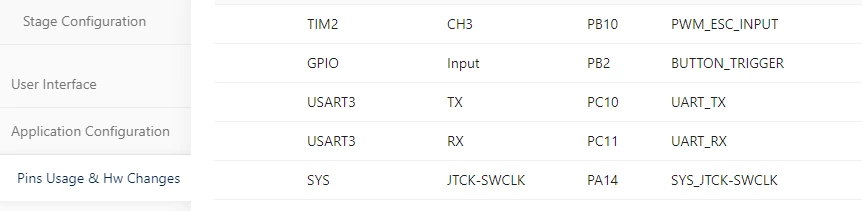
I am using MCSDK 6.4.1 with a custom STM32G431CBUx inverter board. My external ESC PWM signal is physically connected to PB10.

As shown in the two attached images:
1. Motor Control Workbench shows PWM_ESC_INPUT on PB10 / TIM2_CH3.
2. After code generation, STM32CubeMX shows M1_PWM_INPUT on PA15, while PB10 is unconfigured.

Why does the generated configuration differ from the Workbench setting? Is this a known limitation or a configuration issue?

How can I use PB10 / TIM2_CH3 with the native MCSDK ESC functionality?

Thank you.


1 reply

GMA
ST Technical Moderator
October 15, 2026

Hello ​@Iverson,

Thank you for your report.

For STM32G4 series, the TIM2_CH1 input selection on PA15 is forced at project generation.

On STM32G4 reference manual, it is mentioned that: The PWM input mode can be used only with the TIMx_CH1/TIMx_CH2 signals due to the fact that only tim_ti1fp1 and tim_ti2fp2 are connected to the slave mode controller.

Only TIM2_CH3 is available on PB10. 
We will try to further improve the way it is presented to the user.

If you agree with the answer, please accept it by clicking on 'Best answer'.Best regards.GMA