

Initialization issues: PowerStep01
We are using the PowerSTep01 chip to control a stepper motor.
https://www.st.com/resource/en/datasheet/powerstep01.pdf
Recently we have had issues with the control of motors where the initialization of the PowerStep01 chip failed at startup and the status register read 0x0000 before initialization and 0xE603 after initialization and 0xE613(HiZ=1) when tried to run the motor.
After some investigation we figured that sending a reset pulse for 5ms worked (initial Solution A) which had to be increased to 100ms (Solution B) for a stable outcome.
The solution was built by reading through the answers in different forums, with 2 examples links below
- https://forums.parallax.com/discussion/165132/trouble-driving-the-powerstep01-using-the-x-nucleo-ihm03a1expansion-board
- https://community.st.com/power-management-53/powerstep01-constantly-tripping-overcurrent-25813
Below is the detailed problem description as well as details of solution A and B. The problem resurfaced after removing intermediatory fixes done while reaching Solution A. We landed onto solution B to solve the new problem.
We would like to understand the root cause of the original problem and what made the solution work.
We also would like to understand why the solution resurfaced again after solution A (described below) and if the solution B matches the expected usage.
Note: The STBY/RESET Pin 10 pin is pulled down by hardware configuration , which means that by default the PowerStep01 chip is configured to DISABLE the motor operation. When required to operate the motor, this pin is set to HIGH via software control.
Problem description
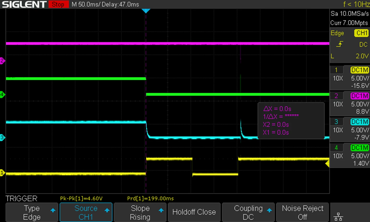
- The STBY/RESET pin is set to LOW by hardware configuration before it is set to LOW again by software control through a controller chip.
- This is observed in the blue line during the first 3 grid blocks in GRAPH 01 below, where the pin is set to low first and there is a slight dip in the LOW voltage which marks the point where the pin is set to LOW using the controller chip software.
- To perform the initialization of PowerStep01 chip, the STBY/RESET pin is set to HIGH and the status register 0x0D is read as the first step of initialization.
- PowerStep01 responds with 0x0000 as the status register value which suggests that the chip is in a faulty state.
- This is seen in the pink MISO line in GRAPH02 which is a response to reading of 0x0D status register on green line in GRAPH 02
- PowerStep01 responds with 0x0000 as the status register value which suggests that the chip is in a faulty state.
- When the PowerStep01 chip is in this state, the initialization sequence fails, and it does not respond to any other motor control commands.
- This only happens on some devices and on some other devices the same initialization sequence works fine.
Legend for the graph 01
- Blue : STBY/RESET Pin 10
- Yellow : Clock
- Green : MOSI
- Pink: MISO
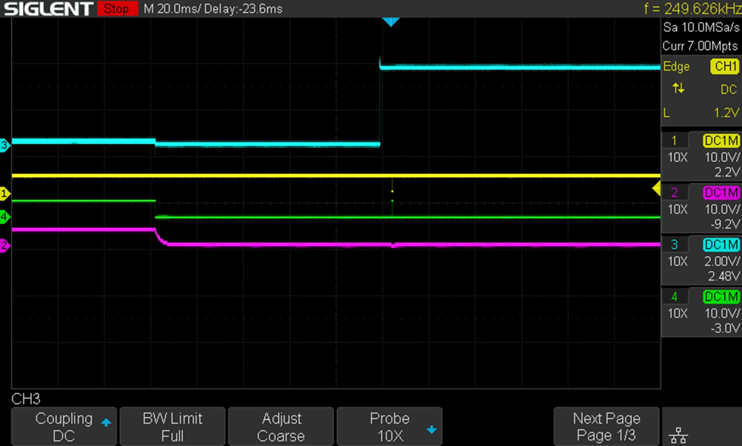
GRAPH 01
Legend for the graph 02
- Blue : CHIP SELECT
- Yellow : Clock
- Green : MOSI
- Pink: MISO
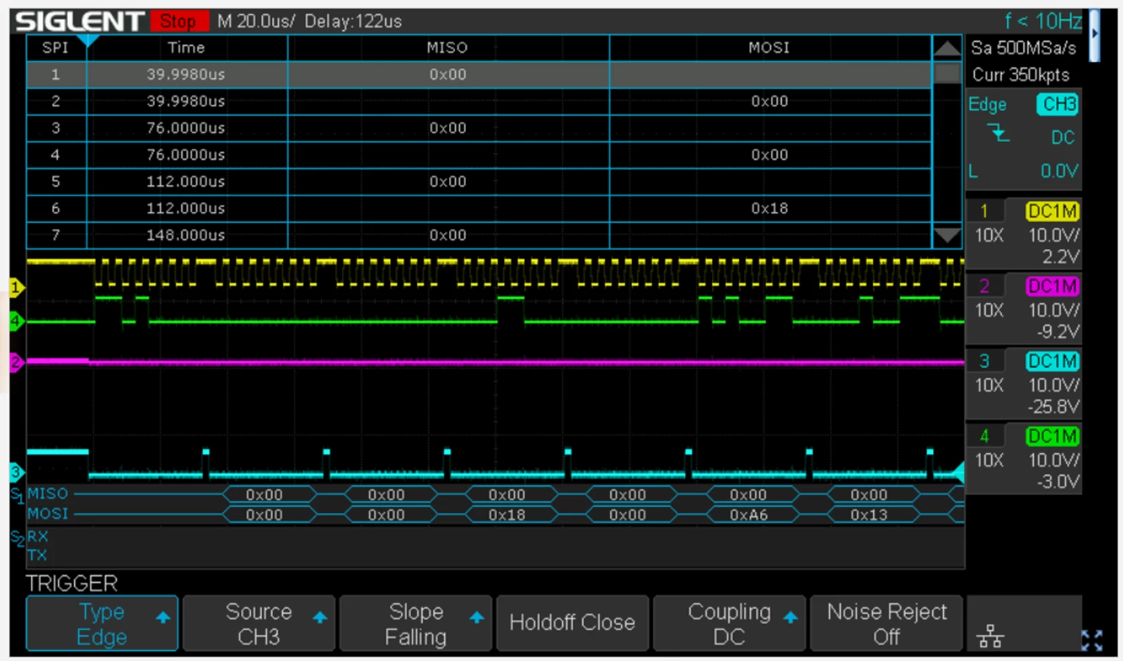
GRAPH 02
Solution A
Note: The legend colors have changed compared to GRAPH01
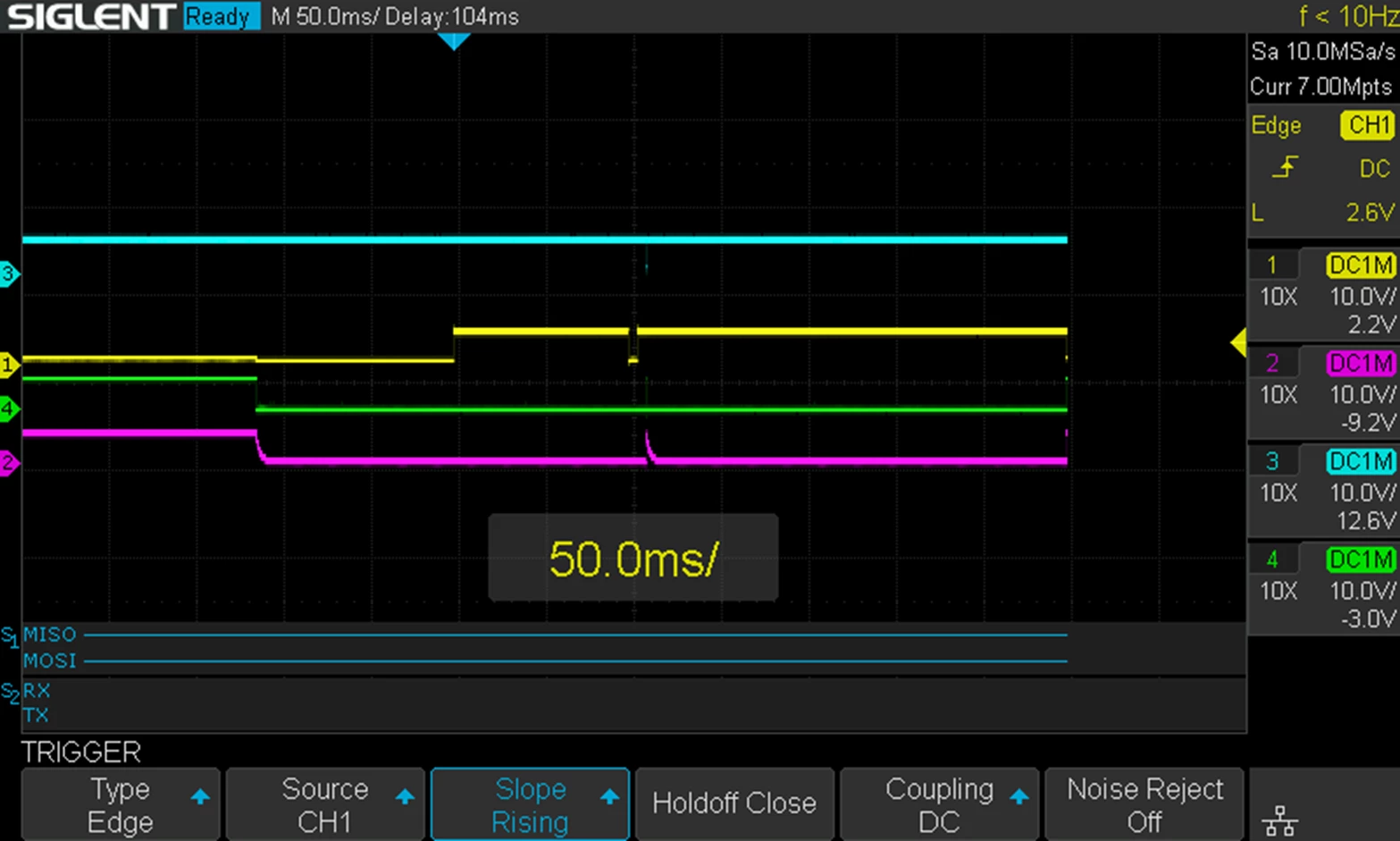
Based on information gather from forums, a reset pulse was introduced into the startup sequence as seen in the GRAPH03 below
- The initial situation is same as in GRAPH01
- Power-up starts with a hardware pulldown to LOW, followed by a Software controlled pull down through a controller chip seen as the slight dip in the yellow line.
- 100ms into the software-controlled pulldown to LOW, the STBY/RESET Pin is set to HIGH for 100ms and then set to LOW again for 5ms.
- This is the additional reset pulse based on info gathered from different forums
- After the 5ms setting of STBY/RESET Pin 10 to LOW, this pin is set to HIGH again and the initialization step is carried as done in step 2 in problem description chapter.
- Reading status register 0x0D, and PowerStep01 responds with 0xE603 (The compressed pink spike in GRAPH03 below)
- From this stage onwards the PopwerStep01 chip works as expected, and status register reads 0xE712 when tried to run the motor.
Legend for the graph 03
- Blue : CHIP SELECT
- Yellow : STBY/RESET Pin 10
- Green : MOSI
- Pink: MISO
Need for Solution B
- The solution A had one of the temporary fix attempts where the initial software-controlled setting of STBY/RESET pin to LOW was delayed for about 1-2 seconds after power-up.
- When Solution A worked, this temporary solution was removed, and initial software-controlled setting of STBY/RESET pin was done soon after powerup. This also means that the graph does not capture(due to time solution settings of the oscilloscope) the slight dip in LOW voltage when transitioning from Hardware pull down to LOW and software-controlled transition to LOW
- This meant that now the software-controlled pull down of STBY/RESET was done longer than in Solution A.
- Initially this pin is pulldown to LOW
- The controller chip then pulls it down to LOW for about 800-1000ms
- The pin is set to HIGH for 100ms before setting it to LOW again for 5ms (Yellow Line)
- The pin is then set to HIGH and Initialization sequence is performed which seems to fail again.
- In this state PowerStep01 responded with 0xE603 to status register read.
- But when attempting to run the motor the status register reported 0xE613 (HiZ)
- The original problem now resurfaces again, although not 100% exactly as the original problem but the consequence is the same i.e., motor does not rotate.
Legend for the graph 04
- Blue : MISO
- Yellow : STBY/RESET Pin 10
- Green : MOSI
- Pink: ChipSelect
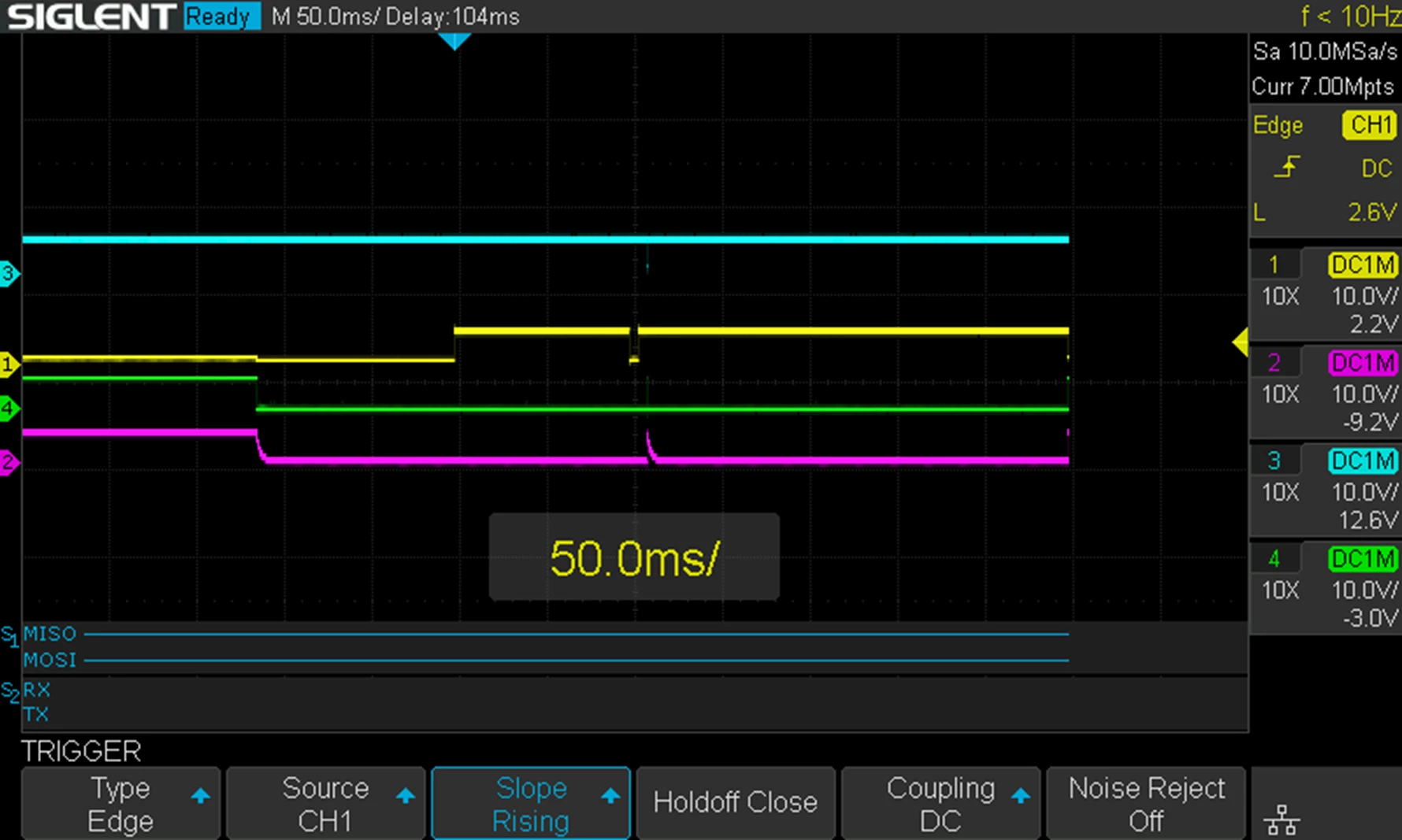
Solution B
- The new problem is solved increasing the setting of STBY/RESET pin to LOW from 5ms to 100ms
- Initially this pin is pulldown to LOW
- The controller chip then pulls it down to LOW for about 800-1000ms (as before)
- The pin is set to HIGH for 100ms before setting it to LOW again for 100ms (Yellow Line)
- The pin is then set to HIGH, and the initialization sequence is performed.
- The setup works as expected and is stable.
Legend for the graph 05
- Blue : MISO
- Yellow : STBY/RESET Pin 10
- Green : MOSI
- Pink: ChipSelect
Status Register values
0xE003
This state is reported sometimes. It is a faulty state
Status Register: 0xE003 (Binary: 11100000 00000011)
==========================================================================================
BIT | FLAG | RAW | FUNCTIONAL DESCRIPTION
------------------------------------------------------------------------------------------
Bit 15 | STALL_A | 1 | Normal. No motor stall detected on Phase A.
Bit 14 | STALL_B | 1 | Normal. No motor stall detected on Phase B.
Bit 13 | OCD | 1 | Normal. Current flowing through power MOSFETs is within safe limits.
Bit 12:11 | TH_STATUS | 0 | Normal Temperature. Chip junction temperature is within safe limits.
Bit 10 | UVLO_ADC | 0 | FAULT: ADC Under-Voltage Lockout active.
Bit 9 | UVLO | 0 | FAULT: Supply Under-Voltage Lockout (Vs too low)!
Bit 8 | STCK_MOD | 0 | Inactive. Device is running under standard SPI command mode.
Bit 7 | CMD_ERROR | 0 | Normal. No command sequence execution errors.
Bit 6:5 | MOT_STATUS | 0 | Stopped. The motor is holding position or in high-impedance mode.
Bit 4 | DIR | 0 | Reverse (Counter-clockwise movement pattern).
Bit 3 | SW_EVN | 0 | No external switch trigger events logged.
Bit 2 | SW_F | 0 | Switch open / inactive.
Bit 1 | BUSY | 1 | Ready. Core is idle and waiting for incoming commands.
Bit 0 | HiZ | 1 | Bridges Disabled. Outputs are at High Impedance (motor is free-spinning).
==========================================================================================
0xE603
In this state the PowerStep is ready to accept RUN request. This state itself does not allow the motor to run due to the HiZ at the outputs. The motor is rotatable by hand,
Status Register: 0xE603 (Binary: 11100110 00000011)
==========================================================================================
BIT | FLAG | RAW | FUNCTIONAL DESCRIPTION
------------------------------------------------------------------------------------------
Bit 15 | STALL_A | 1 | Normal. No motor stall detected on Phase A.
Bit 14 | STALL_B | 1 | Normal. No motor stall detected on Phase B.
Bit 13 | OCD | 1 | Normal. Current flowing through power MOSFETs is within safe limits.
Bit 12:11 | TH_STATUS | 0 | Normal Temperature. Chip junction temperature is within safe limits.
Bit 10 | UVLO_ADC | 1 | Normal. Internal ADC reference voltage is stable.
Bit 9 | UVLO | 1 | Normal. Main supply voltage (Vs) is above operating threshold.
Bit 8 | STCK_MOD | 0 | Inactive. Device is running under standard SPI command mode.
Bit 7 | CMD_ERROR | 0 | Normal. No command sequence execution errors.
Bit 6:5 | MOT_STATUS | 0 | Stopped. The motor is holding position or in high-impedance mode.
Bit 4 | DIR | 0 | Reverse (Counter-clockwise movement pattern).
Bit 3 | SW_EVN | 0 | No external switch trigger events logged.
Bit 2 | SW_F | 0 | Switch open / inactive.
Bit 1 | BUSY | 1 | Ready. Core is idle and waiting for incoming commands.
Bit 0 | HiZ | 1 | Bridges Disabled. Outputs are at High Impedance (motor is free spinning).
==========================================================================================
0xE712
Status Register: 0xE712 (Binary: 11100111 00010010)
==========================================================================================
BIT | FLAG | RAW | FUNCTIONAL DESCRIPTION
------------------------------------------------------------------------------------------
Bit 15 | STALL_A | 1 | Normal. No motor stall detected on Phase A.
Bit 14 | STALL_B | 1 | Normal. No motor stall detected on Phase B.
Bit 13 | OCD | 1 | Normal. Current flowing through power MOSFETs is within safe limits.
Bit 12:11 | TH_STATUS | 0 | Normal Temperature. Chip junction temperature is within safe limits.
Bit 10 | UVLO_ADC | 1 | Normal. Internal ADC reference voltage is stable.
Bit 9 | UVLO | 1 | Normal. Main supply voltage (Vs) is above operating threshold.
Bit 8 | STCK_MOD | 1 | Active. Device stepping is driven via external clock signal (STCK pin).
Bit 7 | CMD_ERROR | 0 | Normal. No command sequence execution errors.
Bit 6:5 | MOT_STATUS | 0 | Stopped. The motor is holding position or in high-impedance mode.
Bit 4 | DIR | 1 | Forward (Clockwise movement pattern).
Bit 3 | SW_EVN | 0 | No external switch trigger events logged.
Bit 2 | SW_F | 0 | Switch open / inactive.
Bit 1 | BUSY | 1 | Ready. Core is idle and waiting for incoming commands.
Bit 0 | HiZ | 0 | Bridges Active. Coils are energized and output power is enabled.
==========================================================================================