how to reduce back-EMF voltage when appling six-step commutation for BLDC motor?
Hello,
I'm using F429 to control BLDC motor with 6step_lib on my drive board.
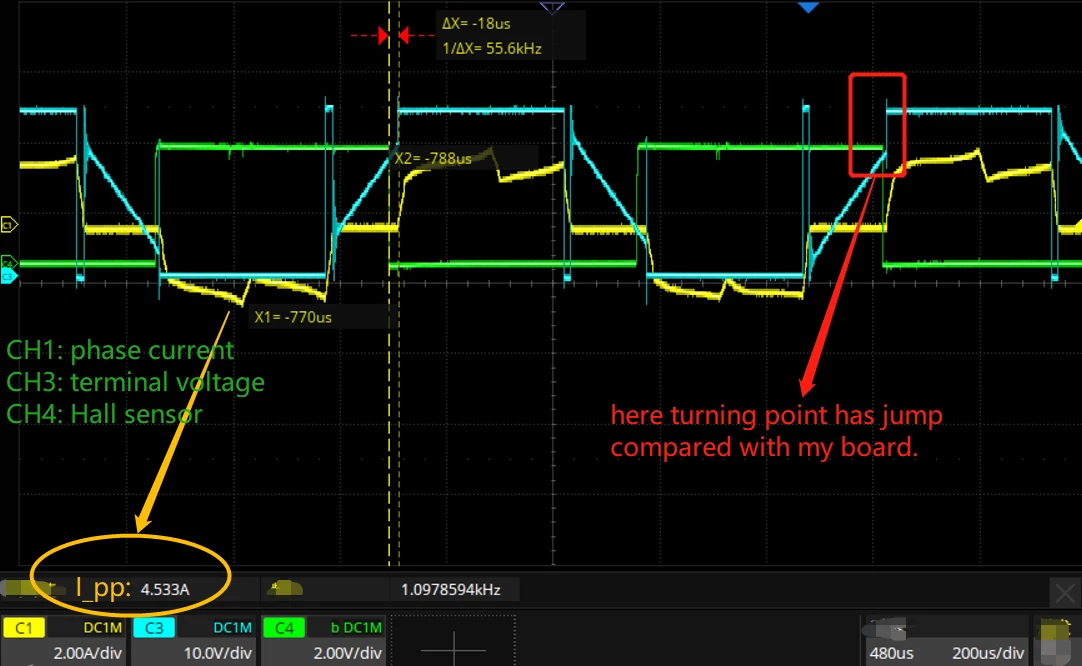
But compared to the other ESC board sold on market, my drive has higher current:
I write TIM1 registers such as CCRx and CCER when HALL sensor edges triggering. And uncomplementary PWM for 6step.c.
My peak-peak current are about 1 Ampere bigger than other ESC drive board when dragging the same bldc motor at full speed. I attached captures of one phase current, its hall sensor and terminal Voltage of my board and the other ESC board separately. I don't know where consume this 1A current.
I suppose that the other drive board may apply some "field weaken" technique because I found the terminal voltage has jump at turning point showed in second capture, however, I'm also confused that THIS voltage does not advance hall sensor . My board has no voltage jump at turning point showed in first capture.
regards,
my drive board:
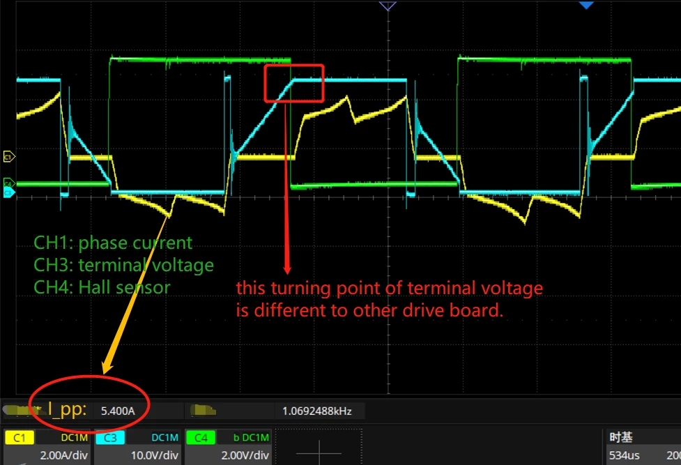
the other ESC board: