How to enable the timer channels to follow the correct PWM Schemes
Hi All,
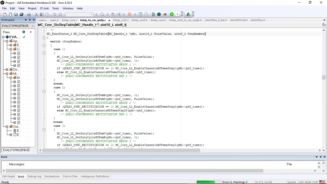
Can anyone help me decipher exactly what is going on in this piece of code. It is meant to be a H-PWM,L-ON scheme meaning at any hall status step, the high side switch of one leg of my inverter is pulsed while the low side switch of the other leg of my inverter is just switched. This is shown in the first picture under case1,case2,...,case6
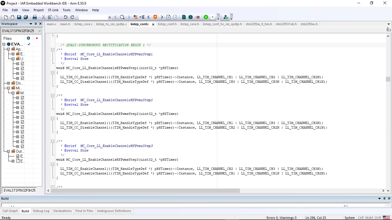
Now, this would mean that I only need to enable the timer (in this case timer 1) channel that corresponds to the high side switch of one leg and the low side switch of the other leg while disabling the remaining switches. This is shown in second picture under the functions MC_Core_LL_EnableChannelsHfPwmsStep1(uint32_t *pHfTimer) etc.
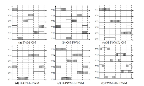
The main reason I needed to figure this out is that I am trying to implement other PWM schemes as shown in the third picture. But the code does not respond.
Apparently, the channel enabling is meant to be done by adjusting the CCER, but based on this code it is just not rightly adjusted but it works. It is a 16bit timer and I am using the STM32F031C6TX.
My overall point: I would really appreciate some help on how to properly enable the right channels. For example, in step 1, it does not make any sense as to why a channel (CH2) and its complementary channel (CH2N) should be enabled at the same time in the software. But on checking the actual pulses on the inverter legs, they are never enabled at the same time because that would make that leg short-circuit current to ground.
P.S: I am not an embedded software guy, just an electronics guy trying to graduate loool.