

Engine stalled due to undervoltage or overheating
Hello everyone, I have successfully controlled the Lin Engineering BL23E3301D04RO motor with the Nucleo-G474RE and IHM08M1 inverter .. using FOC configured in MC Workbench and the motor’s built-in encoder.
I then copied the entire project and changed only the engine.
Now I’m having trouble getting the following PMSM motor to run.
-
Kt — 1.54 N·m/Arms
-
Motor Constant Km— 1.63 Nm/sqrt(watt)
-
RM (lin to line) at Amb — 0.60 Ohms
-
Inductance — 2.24 mH
-
Motor Poles — 16
-
Ipeak Motor — 51.19 Arms
-
Tcont Stall — 20.74 N·m
-
Icont Stall Motor — 13.60 Arms
-
Tpk motor (25°C) — 64.54 Nm
-
Rated speed — 1914 rpm
-
Rated Power — 2826 W
-
Inertia (KBM) — 5.69E-3 Kg-m² (4.20E-3 lb-ft-s²)
-
Max Static Friction — 0.203 Nm (0.150 lb-ft)
-
Cogging Friction — 0.102 Nm (0.075 lb-ft)
-
Poles — 16
-
Back EMF Constant — 93.3 Vrms/kRPM
In MC Workbench, I have set the following:
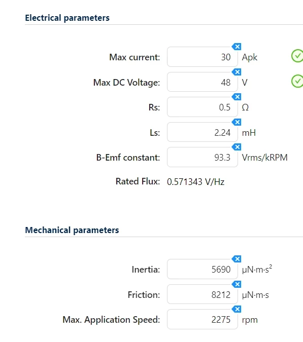
I have configured the quadrature encoder to 2000 pulses per mechanical revolution.
The power supply is CPX400S:
- Vout — 46V
- Iout,max — 5A
I’ll break down the tests I’ve carried out below so we can understand them better.
----------------------------------------------------------------MC Workbench----------------------------------------------------------------
PROBLEM no.1: the motor gives a slight initial jolt, then stops (making a noise); the current supplied by the power supply increases and the power supply voltage drops until an undervoltage fault occurs. If I let the current rise, I’ll burn out the IHM driver (it’s happened before).
I have NOT tried sensorless mode (I was getting feedback errors and didn’t try adjusting all the various parameters) and I’m using this encoder. I am required to use the Encoder in the final application so I’d like to sort the problem out with him.
I don’t think it’s a PID issue, both because I’ve tried various settings and the situation hasn’t changed… and because it seems that something else is blocking the motor; the PID tries to push it to the limit by demanding maximum output, but the motor remains stationary.
TEST: trying to change the speed PID parameters and cut-off frequency of the current loop does not seem to solve the problem. In the current loop, the motor either remains stationary or behaves in the same way of the speed loop.
My application has a maximum speed of 250 rpm (even though the engine can reach 2000rpm), so this immediately raises the first question:
- Which parameter in MC Workbench should be set to 250 rpm? The ‘Target speed’ in the Speed Regulator?
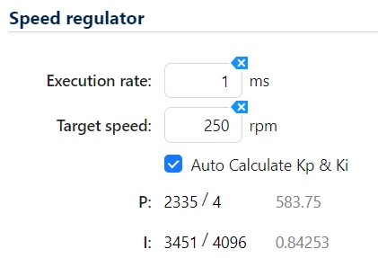
SUSPECT no.1: I don’t know if this has anything to do with it, but (if I remember correctly) when I was using the Lin Engineering BL23E3301D04RO motor on the oscilloscope, with the probe connected to the encoder’s A pulse, I could see a clear signal… now I see completely distorted, unrecognisable pulses. I admit that the encoder cables (mounted on the motor shaft) were cut, soldered to a further 4–5 cm of cable and then adapted (crimped and fitted with a connector) to connect them to the connector on the IHM08M1.
SUSPECT no.2: if I set the quadrature encoder to 1000 pulses per mechanical revolution (and not 2000 as it should be) the motor runs smoothly at a speed that is double (or triple – I can’t remember) the set speed. I’m not surprised that the speed is different… but I am surprised that the motor runs without any problems!
----------------------------------------------------------------Motor Profiler----------------------------------------------------------------
SUSPECT no.3: are the motor parameters correct? “It’s good to trust the datasheet, but better not to” – so I’ve decided to estimate them using your Motor Profiler (thereby switching to sensorless control). Here too, I’m not quite sure what values to set for ‘Max Speed’ and ‘Max Current’ for the estimation… the motor’s maximum values? Or the maximum values I set on the bench-top power supply? This test leads to another problem:
PROBLEM no.2: at around 28%, the profiler ‘freezes’ – that is, the motor accelerates for a few seconds, then stops abruptly, then starts turning again for a few seconds, then stops abruptly, and so on, until it triggers an overheating fault. I’ve tried both the motor’s rated current (minus 15%) … and 5A (well below the motor’s 50Apk) … but the problem persists.
SUSPECT no.4: the motor isn’t completely ‘idling’ – that is, it has a shaft and is mounted within a mechanical structure, so it has a bit of load torque… I hope that isn’t a problem for the Motor Profiler.
----------------------------------------------------------------CONCLUSIONS----------------------------------------------------------------
I’m wondering what might be causing these two issues… In the meantime, I’m continuing to adjust the parameters in MC Workbench and monitor them using CubeMonitor.
If there are any specific parameters you’d like to know about or see, just let me know which ones and I’ll plot them and attach screenshots, updating the main post.