

Encoder reliability and false errors on start-up
I’m using X-NUCLEO-IHM08M1 with NUCLEO-G474RE evaluation board for FOC speed control of PMSMs.
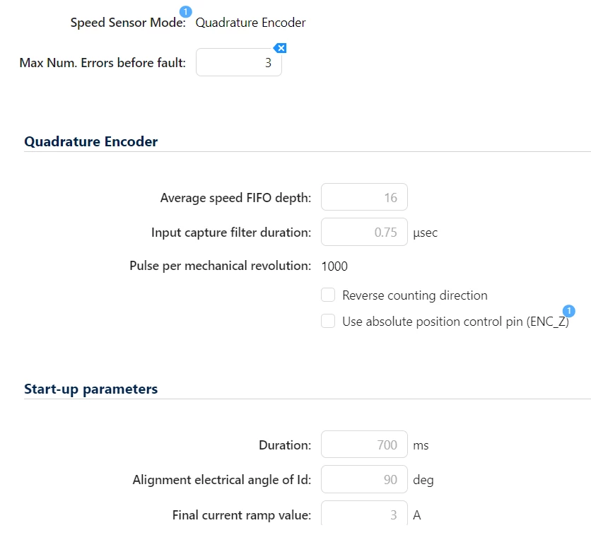
My main sensor is SE461000AB10030 encoder (I do not intend to use a sensorless system) and I’ve set it to 1000 ppr on the MC Workbench. With other commercial inverters, I’ve always used it with only its A, B and Z outputs (not the differential inverted ones)
When I power up via usb the evaluation board (DC bus off), I turn the rotor with my hand and connect the oscilloscope to CN7_17 and CN10_31, I can see the encoder pulses correctly; and when I turn the encoder by hand through one mechanical revolution (360 degree), TIM2->CNT goes from 0 to 4000, as it should.
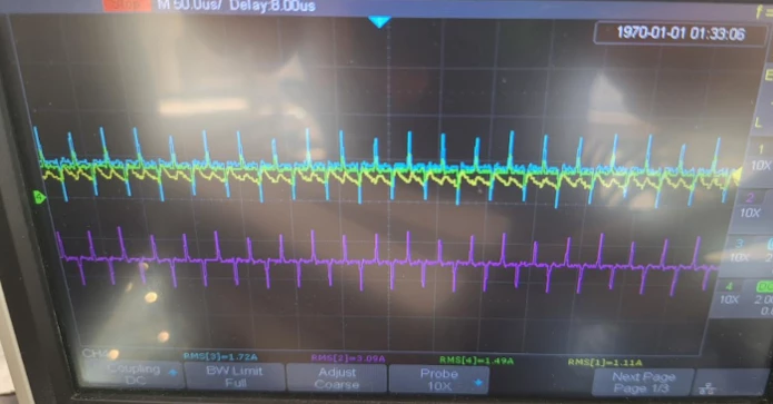
The problem is that as soon as I press START (blue push botton), the rotor gives a brief slow jolt, the state machine switches to “alignment” and finally enters “run” mode without any faults; the currents across the three phases are these but the rotor is stuck (it isn't moving...)
On the hardware side, I followed the changes that MC Workbench advises you to make before generating code, and the problem persists whether JP3 is enabled or not.
The only instruction I have in main.c after USER CODE BEGIN 2 is MC_ProgramSpeedRampMotor1(20, 2000) with #define SPEED_UNIT U_RPM.
These two functions return the same value (for less than 1 second because the rotor is stationary...):
- control_el_angle = MCI_GetElAngledpp(&Mci[0]);
- ENCODER_el_angle = SPD_GetElAngle((SpeednPosFdbk_Handle_t *)&ENCODER_M1);
The function ENCODER_speed = SPD_GetAvrgMecSpeedUnit return 0 (always)
angle_error_deg The figure calculated below ranges from 0 to -172:
- angle_error = (int16_t)(STOPLL_el_angle - ENCODER_el_angle);
- angle_error_deg = ((float)angle_error * 360.0f) / 65536.0f;
The function isSensorOK = MCI_GetSpdSensorReliability is true at the beginning but the became false
The variable `phase_current_ampl_A` = 3A and corresponds to the 3A set as the alignment in MC Workbench:
- phase_current_ampl_s16a = MCI_GetPhaseCurrentAmplitude(pMCI[M1]);
- phase_current_ampl_A = (phase_current_ampl_s16a * 3.3) / (65536 * 0.01 * 5.18);
The ‘Reverse counting direction’ option does not change anything; the rotor remains stuck.
However, I’ve noticed something strange when I press the green arrow ‘resume’, without even pressing the blue ‘start’ button on the evaluation board, in the Live Expressions I see:
- hMinReliableMecSpeedUnit = 0
- hMaxReliableMecSpeedUnit = 345 (I’d say that’s correct because I’ve set it up 300rpm * 1.15)
- hMaxReliableMecAccelUnitP = 65535
- bMaximumSpeedErrorsNumber = 3
- TimerOverflowError = false
- TimerOverflowNb = 0
It seems strange to me that bMaximumSpeedErrorsNumber = 3 … and it always happens: as soon as I press the reset button (the black one), it immediately goes back to 3.
I’m asking for help because I don’t know what tests to do next.
Thanks.
------------------------------------------------------------UPDATE----------------------------------------------------------------------
As a last-ditch attempt, I swapped the red and green wires – that is, I switched pulse A and B, even though this goes against what is stated in the encoder’s datasheet – and the rotor started to rotate smoothly before coming to a halt after about 10 seconds due to an overcurrent fault.
So at the moment, I’m not sure whether to leave the wires swapped like this and carry on, or to put them back in their original positions and sort out the problem…