Encoder counts varying when on pwm
I am testing Rhino encoder motors(ig32) 100rpm on an STM32H723ZG Nucleo-144.
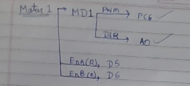
my actual connections are:
Motor driver PWM  → PC6  → TIM8_CH1
Motor driver DIR  → A0   → PA3

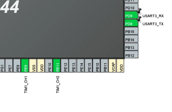
Encoder A → D5 → PE11 → TIM1_CH2
Encoder B → D6 → PE9  → TIM1_CH1
my confirmed the CubeMX configuration shows:
TIM1 Encoder Mode = TI1 + TI2
PE9  = TIM1_CH1
PE11 = TIM1_CH2
So the encoder is a genuine quadrature encoder, and I have intentionally kept TI12 rather than switching permanently to TI1.
2. Motor encoder specification
Rhino RMCS-5031 datasheet.
The datasheet specifies:
- Gear ratio: 1:174
- Encoder type: Quadrature
- Output-shaft CPR listed as 9048
- Base Hall sensor count: 13
The relationship is:
13×174=226213\times174=2262
and with 4× quadrature decoding:
2262×4=90482262\times4=9048
So the manufacturer's 9048 figure and my observed quadrature counts became an important part of the investigation.
3. my original problem
I originally wanted the motor to:
rotate exactly one output-shaft revolution and stop based on encoder counts.
i initially estimated:
CPR = 157367from an earlier experiment involving about 3.5 turns.
I then put 157367 into the motor-stop code.
The motor ran roughly one physical revolution before stopping around:
160674and another run stopped around:
160557At first this looked like my CPR was approximately 160,600, but later testing showed that was not a valid CPR determination.
4. The 16-bit TIM1 problem
my TIM1 configuration uses:
htim1.Init.Period = 65535;so TIM1 is a 16-bit counter.
That means it naturally does:
0 → 65535 → 0 → 65535 ...myraw counter output showed this clearly:
64807
64804
...
124
1569
...
The transition from approximately 65000 back to a small number was simply counter rollover.
I therefore added a software 32-bit accumulator so the total count could continue across TIM1 overflow.
That accumulator was later verified to work correctly.
For example:
Raw ≈ 34532
Total = 165604
because:
65536+65536+34532=16560465536+65536+34532=165604
So the rollover software itself was not the cause of the huge count discrepancy.
5. My manual test
This became the most important reference.
I physically attached the wheel to the gearbox output shaft and rotated the wheel/output shaft manually by one complete revolution.
With TIM1 configured as:
TIM_ENCODERMODE_TI12you observed approximately:
36192 countsThis is exactly:
9048×4=36192
So my manual test established:
One complete output-shaft/wheel revolution gives approximately 36,192 timer counts in your current TI12 configuration.
6. The strange motor behavior
The real problem appeared when the motor was electrically running.
With:
#define CPR 36192and TI12 quadrature decoding, the motor would reach about:
36192 countswhile the wheel/output shaft had moved only around one quarter of a revolution.
I observed examples like:
40750
45985
51119
56246
61254
and explained that the motor had not even completed one full revolution.
This was the central mystery:
Manual rotation:
1 full output revolution ≈ 36192 counts

Motor powered:
~1/4 output revolution ≈ 36192 counts
7. I tested motor running without a stopping target
To remove the possibility that the stop code itself was causing the problem, we created a no-stop motor test.
The motor ran continuously at about 10% PWM, while the encoder counter was printed.
The counter increased smoothly:
0
980
1960
3154
...
35976
37188
38212
...
64807
420
1569
...
This showed:
- TIM1 was actively counting.
- The 16-bit rollover was happening normally.
- The count was not simply stuck.
- The motor was producing a large stream of encoder counts.
8. USER-button stop test
I then added the NUCLEO USER/B1 button so you could stop the motor manually.
That produced:
Final raw TIM1 count: 34532
Final accumulated encoder count: 165604
and later another run gave:
Final raw TIM1 count: 40664
Final accumulated encoder count: 171736
I pointed out that me myself had only let the wheel make about one physical revolution before pressing the button, but the accumulator was around 165k–172k.
This reinforced that the powered motor was producing far more counts than expected.
my chatbot also recognized that using a human button press is not a precise calibration method, because you can't stop exactly at one physical revolution every time. You were absolutely right about that.
9. TI1 experiment
I then changed the encoder mode temporarily from:
TIM_ENCODERMODE_TI12to:
TIM_ENCODERMODE_TI1to see whether using only one channel for counting would resolve the problem.
During that test, I got:
Final encoder count: 19210for roughly one physical output-shaft revolution using the USER button.
then i saw that it only moved approx ¼ rth turns
That made perfect sense relative to:
36192/9048 = 436192/9048=4
So I concluded:
TI12 + target 9048 → ~1/4 revolution
TI12 + target 36192 → expected ~1 full revolution
Thus TI12 itself was not the obvious error.
I wanted to stay on TI12 and rising-edge configuration, which is currently the direction we're following.
10. Encoder diagnostic test
I created a diagnostic program that printed:
Raw TIM1 counter
Delta
Accumulated count
A = PE11
B = PE9
The powered run showed steadily increasing counts such as:
Raw: 35650
Raw: 36674
Raw: 37688
Raw: 38677
...
with A/B changing through combinations like:
00
01
10
11
That is consistent with a quadrature encoder signal.
The accumulator also handled rollover correctly.
11. Motor-off test
I then tested the encoder with the motor not moving.
The result stayed completely stable:
Raw: 0
Delta: 0
Total: 0
A: 1
B: 0
for many lines.
This is important because it tells us:
There is not a constant stream of false encoder counts when the motor is stopped.
So the issue is associated with the encoder behavior while the motor is operating, rather than a timer that simply counts by itself.
12. What I currently believe
At the end of the investigation, the remaining issue is:
Why does the encoder count grow about 4× faster than the physical output shaft appears to rotate when the motor is powered?
Possible causes we were considering include:
- electrical interference/noise from the motor/PWM,
- encoder signal integrity,
- encoder output electrical levels/interface,
- how the motor/encoder signals interact under powered operation.
13. Current configuration I consider correct
For now, the intended configuration is:
Encoder mode: TI1 + TI2
Polarity: Rising
Encoder A: D5 / PE11 / TIM1_CH2
Encoder B: D6 / PE9 / TIM1_CH1

Motor PWM: PC6 / TIM8_CH1
Motor DIR: PA3
And the manually observed TI12 value is:
36192 counts/output-shaft revolution14. Where we left off
The latest diagnostic result showed:
Motor OFF:
Total stays at 0
So the next investigation should focus on what changes electrically when the motor/PWM is turned on, rather than recalculating CPR again.
I was considering testing TIM1 input prescaling/filtering, but that has not been proven to solve the issue yet.
Bottom line
The problem is not simply “what CPR should I enter?”
The strongest evidence currently is:
Manual TI12: 1 wheel revolution≈36192\boxed{\text{Manual TI12: } 1\text{ wheel revolution}\approx36192}
but:
Powered TI12: encoder count rises much faster than physical rotation\boxed{\text{Powered TI12: encoder count rises much faster than physical rotation}}
and the 16-bit rollover problem has already been correctly handled.
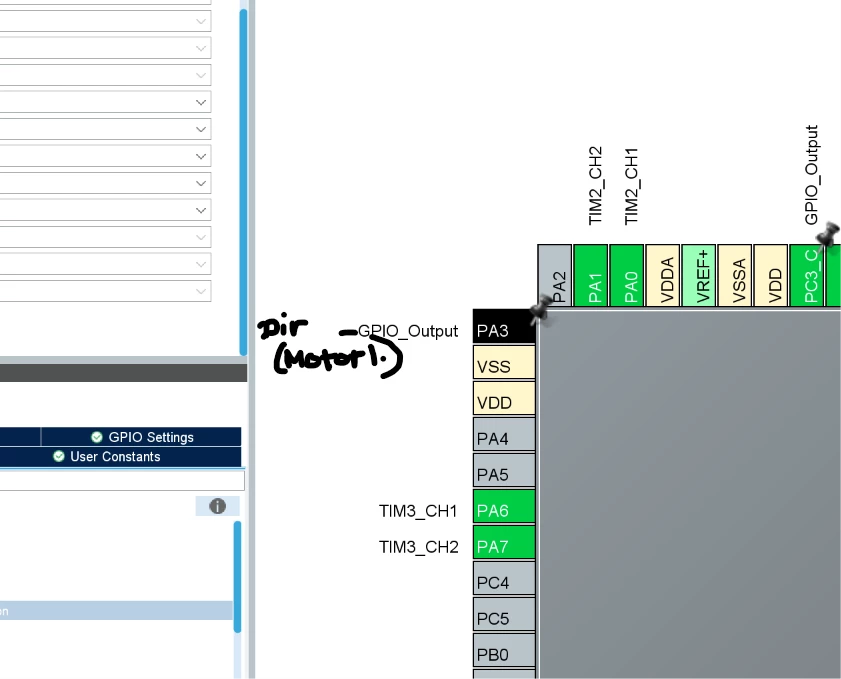
The configuration and pin mapping is attached below.