

What is the relationship between the DAC dataholding registers, data output registers, and the conversion half/full complete callbacks?
Hello everyone
I am having trouble understanding the relationship between the registers and the callback functions for my application. Briefly put, I am transferring 2 values to the DAC via DMA using TIM6 as interrupt at a rate of 50 Hz. I want to sample another value after each of the two DAC values appears at the output, and for that I set flags in the callbacks to start the ADC in my main loop. Intuitively, I would think that HAL_DAC_ConvHalfCpltCallbackCh1 is called after the first value appears at the output, and HAL_DAC_ConvCpltCallbackCh1 is called after the second value appears at the output, but it seems as though the data registers indicate otherwise when I look at the oscilloscope timing diagrams.
The DAC is set up with the following parameters:
- TIM6 trigger out event
- DMA mode circular
TIM6 is set up with the following parameters:
- APB1 timer clock is 84 Mhz
- Prescaler is 8399
- Counter period is 199
- This gives me a 50 Hz interrupt
- Trigger event is set to update event
I start the DAC and TIM6 like this:

And I set a pin to monitor when the callbacks are called:


And another pin in the main while loop to monitor the data registers of the DAC:
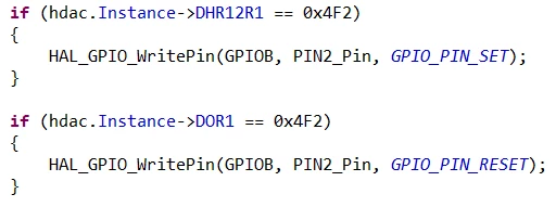
The first values that are loaded into the DAC array are 1266 (0x4F2) and 1216 (0x4C0) which is why I am testing for 0x4F2 above.
On the oscilloscope PIN1 is the yellow line corresponding to when the callbacks are called and the blue line is PIN2 that is toggled when the dataholding and data output register is changed. The image is shown below:
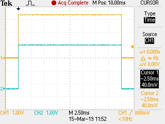
The yellow line is a pulse corresponding to 20 milliseconds as expected (since I toggle it in the half and full complete callbacks of a 50 Hz DAC rate). So according to this figure the HAL_DAC_ConvHalfCpltCallbackCh1 is called almost the same time as the DHR12R1 is changed to 0x4F2. And the HAL_DAC_ConvCpltCallbackCh1 is called almost the same time as the DOR1 register is set to 0x4F2.
I don't know if I am missing something but it seems as though the blue pulse should have appeared before the yellow pulse even started? This is causing all of my samples to be delayed by half a cycle (20ms). The first DAC value that I can measure after the half conversion complete callback is not even 1266 but 0 (or 52 mV in this case due to DAC nonlinearity) as shown below:
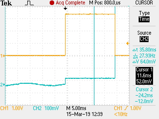
The yellow line is again the pin that is toggled in the callbacks and the blue line in this case is the DAC output. So it seems as though the value of 0 is loaded into the output and only then is 1266 loaded.
Any help would be greatly appreciated (my masters degree depends on it :))
Cheers
