

Senior
June 17, 2026
Solved

USB Host MSC issue with Port Disable continuously

  • June 17, 2026
  • 8 replies
  • 117 views

Hello,
I’m working with custom board STM32F767BITX, trying to interface Standalone USB Host MSC, with no Free RTOS.

Tried different reference, below is one reference which I followed 


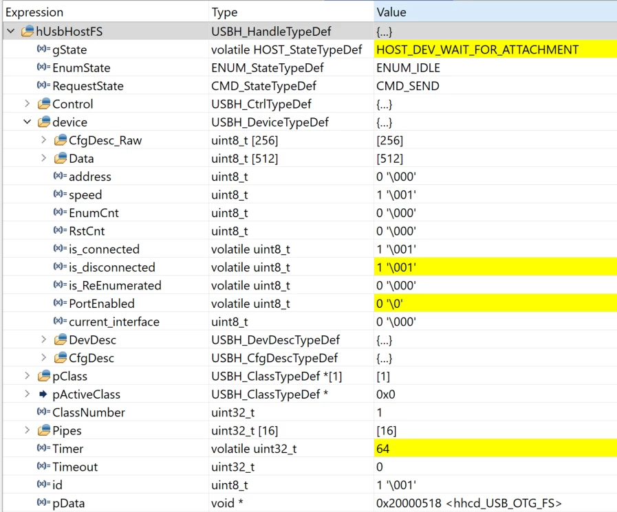
As soon as connected USB, it shows connected but after that it loop between this two calls alternatively, USBH_LL_PortDisabled() and USBH_LL_PortEnabled() which disconnect USB and connect again and continue to do that.

So I dont understand the root cause of this, what trigger this to behave like this?

Please guide me to fix this issue.
 

void SystemClock_Config(void)
{
RCC_OscInitTypeDef RCC_OscInitStruct = {0};
RCC_ClkInitTypeDef RCC_ClkInitStruct = {0};

/** Configure the main internal regulator output voltage
*/
__HAL_RCC_PWR_CLK_ENABLE();
__HAL_PWR_VOLTAGESCALING_CONFIG(PWR_REGULATOR_VOLTAGE_SCALE3);

/** Initializes the RCC Oscillators according to the specified parameters
* in the RCC_OscInitTypeDef structure.
*/
RCC_OscInitStruct.OscillatorType = RCC_OSCILLATORTYPE_HSI|RCC_OSCILLATORTYPE_HSE;
RCC_OscInitStruct.HSEState = RCC_HSE_ON;
RCC_OscInitStruct.HSIState = RCC_HSI_ON;
RCC_OscInitStruct.HSICalibrationValue = RCC_HSICALIBRATION_DEFAULT;
RCC_OscInitStruct.PLL.PLLState = RCC_PLL_ON;
RCC_OscInitStruct.PLL.PLLSource = RCC_PLLSOURCE_HSE;
RCC_OscInitStruct.PLL.PLLM = 15;
RCC_OscInitStruct.PLL.PLLN = 144;
RCC_OscInitStruct.PLL.PLLP = RCC_PLLP_DIV2;
RCC_OscInitStruct.PLL.PLLQ = 5;
RCC_OscInitStruct.PLL.PLLR = 2;
if (HAL_RCC_OscConfig(&RCC_OscInitStruct) != HAL_OK)
{
Error_Handler();
}

/** Initializes the CPU, AHB and APB buses clocks
*/
RCC_ClkInitStruct.ClockType = RCC_CLOCKTYPE_HCLK|RCC_CLOCKTYPE_SYSCLK
|RCC_CLOCKTYPE_PCLK1|RCC_CLOCKTYPE_PCLK2;
RCC_ClkInitStruct.SYSCLKSource = RCC_SYSCLKSOURCE_HSI;
RCC_ClkInitStruct.AHBCLKDivider = RCC_SYSCLK_DIV1;
RCC_ClkInitStruct.APB1CLKDivider = RCC_HCLK_DIV1;
RCC_ClkInitStruct.APB2CLKDivider = RCC_HCLK_DIV1;

if (HAL_RCC_ClockConfig(&RCC_ClkInitStruct, FLASH_LATENCY_0) != HAL_OK)
{
Error_Handler();
}
}


Best answer by npatil15

Hello,

I found the root cause,

The issue is with wrong clock, I mean in the circuit board it has provided 8mhz input frequency, but I have set it to 25mhz which is wrong. Setting correct fix this issue immediately. 

Now able to do all operation with USB.


Thanks

8 replies

ST Technical Moderator
June 17, 2026

Hello ​@npatil15 

Have you tried the example provided in CubeF7. Which clock source are you using for USB?

To give better visibility on the answered topics, please click on "Best answer" on the reply which solved your issue or answered your question.Best regards,FBL
npatil15Author
Senior
June 17, 2026

I have issue while opening that code in STM32CubeIde,

So, asa I open the file .project it gest hanged, so dont understand how top open that project and test it, so I create new project with those reference.

Can you tell me how to open that project or test it in STM32CubeIde?

Pavel A.
June 17, 2026

​@npatil15 This project needs to be converted from SW4STM32 (another Eclipse-like IDE).

In CubeIDE: File→ Import→ Ac6 System …

After conversion, sometimes small adjustments may be needed.


ST Technical Moderator
June 17, 2026

Hi ​@npatil15 

You can either double click on the project and copy project into your workspace or by importing the project :

File > Import… General > Existing Projects into Workspace

I assume you should not select AC6 system workbench (this is an old IDE) use existing project instead.

To give better visibility on the answered topics, please click on "Best answer" on the reply which solved your issue or answered your question.Best regards,FBL
AScha.3
Super User
June 17, 2026

So just show, where is the example for STM-IDE ? (User cannot find it, obviously.)


If you feel a post has answered your question, please click on " Best Answer ".
npatil15AuthorBest answer
Senior
June 19, 2026

Hello,

I found the root cause,

The issue is with wrong clock, I mean in the circuit board it has provided 8mhz input frequency, but I have set it to 25mhz which is wrong. Setting correct fix this issue immediately. 

Now able to do all operation with USB.


Thanks

Visitor II
June 19, 2026

Likely root cause is the USB clock configuration.

For STM32F767 USB Host MSC, the USB peripheral requires an accurate 48 MHz clock. Looking at your PLL settings:

HSE = 25 MHz
PLLM = 15
PLLN = 144
PLLQ = 5

USB clock = (25 / 15 × 144) / 5 = 48 MHz, so on paper it looks correct. However, continuous switching between USBH_LL_PortEnabled() and USBH_LL_PortDisabled() usually indicates one of these issues:

VBUS power instability (most common on custom boards).
Incorrect USB OTG FS/HS hardware connections (DP/DM, ID, VBUS sensing).
Insufficient power supply to the USB device.
Wrong USB clock source or clock instability.
Signal integrity issues (bad PCB routing, missing protection components, poor grounding).

First check VBUS (5V) with a multimeter/oscilloscope while the USB device is connected. If VBUS drops or fluctuates, the host stack will repeatedly disconnect and reconnect the device, causing exactly the behavior you're seeing.

Also verify that USBH_Process() is being called continuously in the main loop and that the USB interrupt is working correctly.

npatil15Author
Senior
June 22, 2026

I agree with your point, but the real issue is not about generating correct 48MHz frequency; it is what external clock source connected to controller.

So as per my custom board it has 8MHz crystal input, in which case I can’t provide 25MHz crystal input for clock configuration.

And that's it, setting 8MHz input clock and generating 48MHz from this fix my issue,