Associate
October 11, 2025
Solved

USB Composite Design (CDC+HID Keyboard)

  • October 11, 2025
  • 5 replies
  • 494 views

Dear STM32 Advisor,


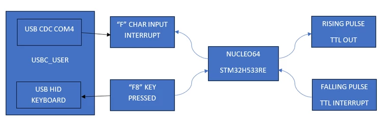
I'll design a system based on Nucleo 64 H533RE. The system will act as USB CDC and USB HID Keyboard at the same time. The idea is when the CDC receive a character, here for example "F" then the Nucleo H533RE will output a high going pulse. And, if the Nucleo H533RE receive falling pulse external interrupt, the the Nucleo H533RE will press the F8 key. As a beginner on STM32, is it possible?

FuadPurnomo_0-1760197412665.png


Thanks and regards,


Fuad Purnomo.

Best answer by FBL

Hi @FuadPurnomo 

Indeed the examples provided by @TDK  are interesting, you need to configure the USB device with two interfaces:

  • CDC ACM interface (for serial communication)
  • HID Keyboard interface (for keyboard reports)

You can refer to this article on how to Implement a USB HID keyboard device USB descriptors must reflect this composite device (2 interfaces). Regarding USBX, examples for CDC ACM exist (e.g., Ux_Device_CDC_ACM example for H533).

  1. Your CDC read thread usbx_cdc_acm_read_thread_entry already reads incoming data into a buffer.
for (int i = 0; i < actual_length; i++)
 {
 if (UserRxBufferFS[i] == 'F')
 {
 // Generate a high-going pulse on a GPIO pin
 HAL_GPIO_WritePin(GPIOx, GPIO_PIN_y, GPIO_PIN_SET);
 HAL_Delay(10); // 10 ms pulse, adjust as needed
 HAL_GPIO_WritePin(GPIOx, GPIO_PIN_y, GPIO_PIN_RESET);
 }
 }

Or triggering a hardware timer or PWM pulse if you want precise timing. 

     2. Adjust function calls based on USBX HID keyboard API. 

 // Prepare keyboard HID report for F8 key press
 keyboardHID keyboardhid = {0};
 keyboardhid.KEYCODE1 = 0x41; // Check HID usage ID for F8 from table section 10 Keyboard/Keypad Page (0x07) in https://usb.org/sites/default/files/hut1_21.pdf
 // Send key press
 ux_device_class_hid_event_set(hid_keyboard, (UX_SLAVE_CLASS_HID_EVENT *)&keyboardhid);
 // Small delay to simulate key press duration to be adjusted to avoid debounce effect 
 HAL_Delay(10);

 // Send key release (all zeros)
 memset(&keyboardhid, 0, sizeof(keyboardhid));
 ux_device_class_hid_event_set(hid_keyboard, (UX_SLAVE_CLASS_HID_EVENT *)&keyboardhid);
 }
}
  • Use HAL_GetTick() or a hardware timer for accurate timing instead of blocking delays.

5 replies

TDK
October 11, 2025

The hardware is capable of doing that.

I recommend buying a nucleo board, getting the existing relevant examples working, then extending it to your use case.

STM32CubeH5/Projects/NUCLEO-H503RB/Applications/USBX/Ux_Device_CDC_ACM at main · STMicroelectronics/STM32CubeH5

STM32CubeH5/Projects/NUCLEO-H563ZI/Applications/USBX/Ux_Device_HID_CDC_ACM at main · STMicroelectronics/STM32CubeH5

"If you feel a post has answered your question, please click ""Accept as Solution""."
FBLBest answer
ST Technical Moderator
October 13, 2025

Hi @FuadPurnomo 

Indeed the examples provided by @TDK  are interesting, you need to configure the USB device with two interfaces:

  • CDC ACM interface (for serial communication)
  • HID Keyboard interface (for keyboard reports)

You can refer to this article on how to Implement a USB HID keyboard device USB descriptors must reflect this composite device (2 interfaces). Regarding USBX, examples for CDC ACM exist (e.g., Ux_Device_CDC_ACM example for H533).

  1. Your CDC read thread usbx_cdc_acm_read_thread_entry already reads incoming data into a buffer.
for (int i = 0; i < actual_length; i++)
 {
 if (UserRxBufferFS[i] == 'F')
 {
 // Generate a high-going pulse on a GPIO pin
 HAL_GPIO_WritePin(GPIOx, GPIO_PIN_y, GPIO_PIN_SET);
 HAL_Delay(10); // 10 ms pulse, adjust as needed
 HAL_GPIO_WritePin(GPIOx, GPIO_PIN_y, GPIO_PIN_RESET);
 }
 }

Or triggering a hardware timer or PWM pulse if you want precise timing. 

     2. Adjust function calls based on USBX HID keyboard API. 

 // Prepare keyboard HID report for F8 key press
 keyboardHID keyboardhid = {0};
 keyboardhid.KEYCODE1 = 0x41; // Check HID usage ID for F8 from table section 10 Keyboard/Keypad Page (0x07) in https://usb.org/sites/default/files/hut1_21.pdf
 // Send key press
 ux_device_class_hid_event_set(hid_keyboard, (UX_SLAVE_CLASS_HID_EVENT *)&keyboardhid);
 // Small delay to simulate key press duration to be adjusted to avoid debounce effect 
 HAL_Delay(10);

 // Send key release (all zeros)
 memset(&keyboardhid, 0, sizeof(keyboardhid));
 ux_device_class_hid_event_set(hid_keyboard, (UX_SLAVE_CLASS_HID_EVENT *)&keyboardhid);
 }
}
  • Use HAL_GetTick() or a hardware timer for accurate timing instead of blocking delays.
To give better visibility on the answered topics, please click on "Best answer" on the reply which solved your issue or answered your question.Best regards,FBL

Andrew Neil
Super User
October 13, 2025

@FuadPurnomo wrote:

As a beginner on STM32, is it possible?


USB is not really a beginner project in any MCU.

So start with the basics first before moving on to advanced topics like USB.

Once you have covered the basics then, as @TDK suggested, start with ST's provided examples to gain familiarity with the STM32 USB ...


A complex system that works is invariably found to have evolved from a simple system that worked.A complex system designed from scratch never works and cannot be patched up to make it work.
Associate
August 9, 2026

Dear all,


Thanks for all of your support. Actually, i’ll develop again this STM32 USBX CDC ACM. First, i inspired by this video 

, then i create my USB CDC ACM project based on that video. But, after upgrading my STM32CUBEMX and STM32CUBEIDE then recreate the USB CDC ACM, the COM won’t be detected by windows. I realized that MX_USBX_Device_Stack_Init() hasn’t called. Then i called the MX_USBX_Device_Stack_Init() inside the app_ux_device_thread_entry:

static VOID app_ux_device_thread_entry(ULONG thread_input)
{
/* USER CODE BEGIN app_ux_device_thread_entry */
TX_PARAMETER_NOT_USED(thread_input);

/* USB_DRD_FS init function */
MX_USB_PCD_Init();

/* Initialize the Stack USB Device*/
if (MX_USBX_Device_Stack_Init() != UX_SUCCESS)
{
/* USER CODE BEGIN MAIN_INITIALIZE_STACK_ERROR */
Error_Handler();
/* USER CODE END MAIN_INITIALIZE_STACK_ERROR */
}

/* Start device USB */
HAL_PCD_Start(&hpcd_USB_DRD_FS);

while(1)
{
tx_thread_sleep(10);
}
/* USER CODE END app_ux_device_thread_entry */
}

The result, COM was listed again on windows device manager. But, the video was just for sending data to PC. Then I change the program to wait receive data from PC. This is part of my code on ux_device_cdc_acm.c

VOID usbx_cdc_acm_read_thread_entry(ULONG thread_input)
{
UX_SLAVE_DEVICE *device;
UCHAR rx_buffer[64];
ULONG actual_length;
UINT status;

TX_PARAMETER_NOT_USED(thread_input);

/* Ambil pointer ke struktur perangkat USB slave utama */
device = &_ux_system_slave->ux_system_slave_device;

while (1)
{
/* PERBAIKAN: Gunakan variabel cdc_acm langsung (diisi saat USBD_CDC_ACM_Activate dipanggil) */
if ((device->ux_slave_device_state == UX_DEVICE_CONFIGURED) && (cdc_acm != UX_NULL))
{
/* Baca data masuk dari USB CDC ACM (Blocking Read) */
status = ux_device_class_cdc_acm_read(cdc_acm, rx_buffer, sizeof(rx_buffer), &actual_length);

if ((status == UX_SUCCESS) && (actual_length > 0))
{
/* 1. Logika Perintah: Kendali LED */
if (rx_buffer[0] == '1' || rx_buffer[0] == 'F' || rx_buffer[0] == 'f')
{
HAL_GPIO_TogglePin(GPIOA, GPIO_PIN_5); /* Sesuaikan Port & Pin LED Anda */
}

/* 2. Kirim kembali data balasan (Echo back) ke PC */
ux_device_class_cdc_acm_write(cdc_acm, rx_buffer, actual_length, &actual_length);
}
}
else
{
/* Jika USB belum siap / terlepas, beri jeda waktu agar tidak membebankan CPU */
tx_thread_sleep(10);
}
}
}

But, everytime i type “F” and [enter], then the STM32CUBEIDE Command Shell Console is hang until hardware Nucleo H533RE is restarted. Dear all, your assistance please...

Associate
August 9, 2026

I also did another try using:

i copy and modified code from here https://github.com/ST-TOMAS-Examples-USB/c071_usbx_cdc.

Here is my part of main.c:

/* USER CODE BEGIN PV */
#define BUFFER_SIZE 32
uint8_t buffer[BUFFER_SIZE];
uint32_t received = 0;
/* USER CODE END PV */

/* Initialize all configured peripherals */
MX_GPIO_Init();
MX_ICACHE_Init();
MX_TIM2_Init();
MX_USBX_Init();
/* USER CODE BEGIN 2 */
MX_USB_PCD_Init();
/* USER CODE END 2 */

/* Infinite loop */
/* USER CODE BEGIN WHILE */
while (1)
{
/* USER CODE END WHILE */
ux_device_stack_tasks_run();
USBD_CDC_ACM_Receive(buffer,BUFFER_SIZE,&received);
if(received!=0)
{
// Periksa apakah karakter yang diterima adalah 'F'
for (uint32_t i = 0; i < BUFFER_SIZE; i++)
{
if (buffer[i] == 'F')
{
// 1. Nyalakan LED di PA5
HAL_GPIO_WritePin(GPIOA, GPIO_PIN_5, GPIO_PIN_SET);

// 2. Reset counter TIM2 = 0 & run TIM2 dg interupsi
__HAL_TIM_SET_COUNTER(&htim2, 0);
HAL_TIM_Base_Start_IT(&htim2);
buffer[i]=0;

break;
}
}
}
/* USER CODE BEGIN 3 */
}

static void MX_USB_PCD_Init(void)
{

/* USER CODE BEGIN USB_Init 0 */

/* USER CODE END USB_Init 0 */

/* USER CODE BEGIN USB_Init 1 */

/* USER CODE END USB_Init 1 */
hpcd_USB_DRD_FS.Instance = USB_DRD_FS;
hpcd_USB_DRD_FS.Init.dev_endpoints = 8;
hpcd_USB_DRD_FS.Init.speed = USBD_FS_SPEED;
hpcd_USB_DRD_FS.Init.phy_itface = PCD_PHY_EMBEDDED;
hpcd_USB_DRD_FS.Init.Sof_enable = DISABLE;
hpcd_USB_DRD_FS.Init.low_power_enable = DISABLE;
hpcd_USB_DRD_FS.Init.lpm_enable = DISABLE;
hpcd_USB_DRD_FS.Init.battery_charging_enable = DISABLE;
hpcd_USB_DRD_FS.Init.vbus_sensing_enable = DISABLE;
hpcd_USB_DRD_FS.Init.bulk_doublebuffer_enable = DISABLE;
hpcd_USB_DRD_FS.Init.iso_singlebuffer_enable = DISABLE;
if (HAL_PCD_Init(&hpcd_USB_DRD_FS) != HAL_OK)
{
Error_Handler();
}
/* USER CODE BEGIN USB_Init 2 */
HAL_PCDEx_PMAConfig(&hpcd_USB_DRD_FS , 0x00 , PCD_SNG_BUF, 0x20);//EP0 OUT
HAL_PCDEx_PMAConfig(&hpcd_USB_DRD_FS , 0x80 , PCD_SNG_BUF, 0x60);//EP0 IN
HAL_PCDEx_PMAConfig(&hpcd_USB_DRD_FS , 0x81 , PCD_SNG_BUF, 0xA0);//EP1 IN
HAL_PCDEx_PMAConfig(&hpcd_USB_DRD_FS , 0x82 , PCD_SNG_BUF, 0xE0);//EP2 IN
HAL_PCDEx_PMAConfig(&hpcd_USB_DRD_FS , 0x03 , PCD_SNG_BUF, 0xF0);//EP3 OUT

_ux_dcd_stm32_initialize((ULONG)NULL, (ULONG)&hpcd_USB_DRD_FS);
HAL_PCD_Start(&hpcd_USB_DRD_FS);
/* USER CODE END USB_Init 2 */

}

void HAL_TIM_PeriodElapsedCallback(TIM_HandleTypeDef *htim)
{
/* USER CODE BEGIN Callback 0 */

/* USER CODE END Callback 0 */
if (htim->Instance == TIM1)
{
HAL_IncTick();
}
/* USER CODE BEGIN Callback 1 */
if (htim->Instance == TIM2)
{
// 1. Matikan LED di PA5 setelah 250 ms berlalu
HAL_GPIO_WritePin(GPIOA, GPIO_PIN_5, GPIO_PIN_RESET);

// 2. Hentikan TIM2
HAL_TIM_Base_Stop_IT(&htim2);
//__HAL_TIM_SET_COUNTER(&htim2, 0);
}
/* USER CODE END Callback 1 */
}

my part of ux_device_cdc_acm.c:

VOID USBD_CDC_ACM_Activate(VOID *cdc_acm_instance)
{
/* USER CODE BEGIN USBD_CDC_ACM_Activate */
UX_PARAMETER_NOT_USED(cdc_acm_instance);
cdc_acm = (UX_SLAVE_CLASS_CDC_ACM*) cdc_acm_instance;
/* USER CODE END USBD_CDC_ACM_Activate */

return;
}

/**
* @brief USBD_CDC_ACM_Deactivate
* This function is called when extraction of a CDC ACM device.
* @param cdc_acm_instance: Pointer to the cdc acm class instance.
* @retval none
*/
VOID USBD_CDC_ACM_Deactivate(VOID *cdc_acm_instance)
{
/* USER CODE BEGIN USBD_CDC_ACM_Deactivate */
UX_PARAMETER_NOT_USED(cdc_acm_instance);
cdc_acm = UX_NULL;
/* USER CODE END USBD_CDC_ACM_Deactivate */

return;
}

/**
* @brief USBD_CDC_ACM_ParameterChange
* This function is invoked to manage the CDC ACM class requests.
* @param cdc_acm_instance: Pointer to the cdc acm class instance.
* @retval none
*/
VOID USBD_CDC_ACM_ParameterChange(VOID *cdc_acm_instance)
{
/* USER CODE BEGIN USBD_CDC_ACM_ParameterChange */
UX_PARAMETER_NOT_USED(cdc_acm_instance);
/* USER CODE END USBD_CDC_ACM_ParameterChange */

return;
}

/* USER CODE BEGIN 1 */
uint32_t USBD_CDC_ACM_Receive(uint8_t* buffer, uint32_t size, uint32_t* received){
if(cdc_acm!=NULL){
ux_device_class_cdc_acm_read_run(cdc_acm,buffer,size,received);
return 0;
}else{
return 1;
}
}
/* USER CODE END 1 */

It is work successfully. the LED PA5 ON after receive “F” and off after 250ms using TIM2. Actually i’d like to upgrade using ThreadX. Dear Master, please guide me.