


Question
timer output channel toggle mode
Hello,
I am using stm32f429zi for my project, I set timer 1 with 4 channels (channel 1 and 2 as input channel, and channel 3 is output channel). I would like to generate a pulse from channel 3 with low frequency and around 50% width to set a communication handshake signal to different control board. I set main frequency as 168MHz, so timer 1 APB2 is 168MHz. the setup is followed:
  TIM_ClockConfigTypeDef sClockSourceConfig = {0};
  TIM_MasterConfigTypeDef sMasterConfig = {0};
  TIM_IC_InitTypeDef sConfigIC = {0};
  TIM_OC_InitTypeDef sConfigOC = {0};


  htim1.Instance = TIM1;
  htim1.Init.Prescaler = 2099;
  htim1.Init.CounterMode = TIM_COUNTERMODE_UP;
  htim1.Init.Period = 65535;
  htim1.Init.ClockDivision = TIM_CLOCKDIVISION_DIV1;
  htim1.Init.RepetitionCounter = 0;
  htim1.Init.AutoReloadPreload = TIM_AUTORELOAD_PRELOAD_DISABLE;
  if (HAL_TIM_Base_Init(&htim1) != HAL_OK)
  {
    Error_Handler();
  }
  sClockSourceConfig.ClockSource = TIM_CLOCKSOURCE_INTERNAL;
  if (HAL_TIM_ConfigClockSource(&htim1, &sClockSourceConfig) != HAL_OK)
  {
    Error_Handler();
  }

  if (HAL_TIM_IC_Init(&htim1) != HAL_OK)
  {
    Error_Handler();
  }
  if (HAL_TIM_OC_Init(&htim1) != HAL_OK)
  {
    Error_Handler();
  }
  sMasterConfig.MasterOutputTrigger = TIM_TRGO_RESET;
  sMasterConfig.MasterSlaveMode = TIM_MASTERSLAVEMODE_DISABLE;
  if (HAL_TIMEx_MasterConfigSynchronization(&htim1, &sMasterConfig) != HAL_OK)
  {
    Error_Handler();
  }
  sConfigIC.ICPolarity =TIM_INPUTCHANNELPOLARITY_RISING;
  sConfigIC.ICSelection = TIM_ICSELECTION_DIRECTTI;
  sConfigIC.ICPrescaler = TIM_ICPSC_DIV1;
  sConfigIC.ICFilter = 0;
  if (HAL_TIM_IC_ConfigChannel(&htim1, &sConfigIC, TIM_CHANNEL_1) != HAL_OK)
  {
    Error_Handler();
  }

  if (HAL_TIM_IC_ConfigChannel(&htim1, &sConfigIC, TIM_CHANNEL_4) != HAL_OK)
  {
    Error_Handler();
  }

//  sConfigIC.ICPolarity = TIM_INPUTCHANNELPOLARITY_FALLING;
//  sConfigIC.ICSelection = TIM_ICSELECTION_INDIRECTTI;
//  if (HAL_TIM_IC_ConfigChannel(&htim1, &sConfigIC, TIM_CHANNEL_2) != HAL_OK)
//  {
//    Error_Handler();
//  }


  sConfigOC.OCMode = TIM_OCMODE_TOGGLE;
  sConfigOC.Pulse = 39999;
  sConfigOC.OCPolarity =TIM_OCPOLARITY_LOW;// TIM_OCPOLARITY_LOW;
  //sConfigOC.OCNPolarity = TIM_OCNPOLARITY_LOW;//TIM_OCNPOLARITY_HIGH;
  sConfigOC.OCFastMode = TIM_OCFAST_DISABLE;
  sConfigOC.OCIdleState = TIM_OCIDLESTATE_SET;

  //sConfigOC.OCNIdleState = TIM_OCNIDLESTATE_RESET;

  if (HAL_TIM_OC_ConfigChannel(&htim1, &sConfigOC, TIM_CHANNEL_3) != HAL_OK)
  {
    Error_Handler();
  }
  __HAL_TIM_MOE_ENABLE(&htim1);
  HAL_TIM_MspPostInit(&htim1);
However, after I start my program, I got the following result:
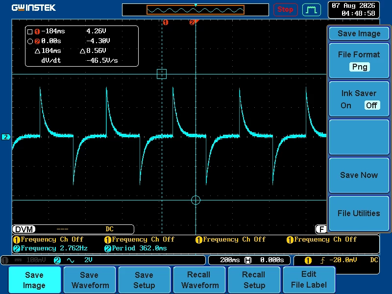
the pulse is not square pulse, the output voltage drops right away after comparator result trigger preset value and toggle output. Does anybody know how to fix this issue? Do I need use pulse output instead of toggle output mode.
thank you.