

Associate II
September 28, 2026
Solved

STM32L4, voltage breakdown on high-impedance ADC input after MX_ADCx_Init

Hello everyone,

I measure a voltage on a STM32L496 using the internal ADC and found the following issue:

Setup:

The voltage is scaled down via a high-impedance voltage divider (2 x 470kOhm). To avoid distortion by sampling, the voltage divider has a 100nF capacitor. Thus, the capacitive load while sampling is low and the breakdown is 1/20000 → i.e. way lower than the ADC’s resolution. So I do not have to care about source impedance limitations as described in the datasheet (Maximum ADC RAIN).

Other data:

  • VREF=VDDA=3.3V (stable)
  • Voltage range of ADC input signal: 0 - 3V (never >3.3V)

Effect:

I experience a large voltage breakdown when I configure the ADC, via CubeMX generated function MX_ADC3_Init (same happens when I use ADC1). I found, that within MX_ADC3_Init the channel gets configured and the ADC sequencer register ADC_SQR1 is set (I only sample that one channel with the high-impedance voltage divider). As soon as ADC_SQR1 is set, the voltage breaks down, from anything >2.5V to approx. 2.5V. When I enable the ADC (ADC_CR.ADEN=1) the breakdown disappears, and there is no more breakdown during sampling (due to high 100nF capacitor). I experience again a breakdown when calling HAL_ADC_DeInit() → ADC is disabled before ADC_SQR1 register is cleared.

Explanation:

Explanation for the above effect is that with ADC_SQR1 being set the external signal is connected to the ADC. Since the ADC is off (ADC_CR.ADEN=0) its state is undefined causing the clipping on the external signal. As soon as the ADC is on everything is defined and ok.

Question:

Is this behavior intended, do you want to fix it, offer a second init-function?

I understand that CubeL4-codes idea is to configure and then to measure. But in case of high impedance sources I find the behavior critical. Anybody experienced the same issue?
 

MarkusVogelBest answer
Associate II
October 14, 2026

Hi ​@Saket_Om ,

you are right, I think this is exactly the effect that I have:

VDD=1.8V

DAC is always off

If ADC is off, voltages are limited to ~2.5V = 1.8V + 0.7V (should be 0.3V acc. to the errata but ok, some limitation)

This goes away if ADC or DAC is enabled. Problem also disappears with ADC_SQRx/JSQRx = 0. So right, my answer is exactly what you wrote in the errata. Thanks for the input and clarification.


Best regards

Markus


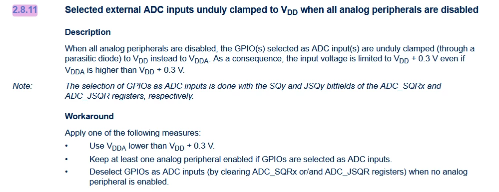
PS: Here is the errata excerpt, mentioned by ​@Saket_Om (ES0335 - Rev 19, p. 21)


20 replies

TDK
September 28, 2026

What is a voltage breakdown in this context?

the breakdown is 1/20000

??

As soon as ADC_SQR1 is set, the voltage breaks down, from anything >2.5V to approx. 2.5V. When I enable the ADC (ADC_CR.ADEN=1) the breakdown disappears

So the “breakdown” is the voltage on the ADC pin drops from 2.5 V - 3.0 V to 2.5 V when setting SQR1? Is the upstream signal low-impedance?

Adding a capacitor will not eliminate the limitations from RAIN, but a voltage divider of 2x470kOhm should be doable at max sampling cycles.

"If you feel a post has answered your question, please click ""Accept as Solution""."
waclawek.jan
Super User
September 28, 2026

> breakdown

maybe “voltage drop”?

2.5V as a limiting value sounds strange in a mcu powered by 3.3V

> When I enable the ADC (ADC_CR.ADEN=1) the breakdown disappears

Are you sure that the described effect is directly related to this bit? You may want to single-step the mcu while observing the registers, or even manually write to the registers in debugger, to observe which operation results in what effect, exactly.

JW

Senior
September 28, 2026

I think the ADC input has a weak pull down resistor internally.  If the port is configured as an input it will float , very high impedance, but when software turns it to ADC alternate function the weak pull down resistor will affect your readings.

The high-impedance voltage divider (2 x 470kOhm) you explain about is very high - the weak pull down will cause a shift.

Can you use lower value resistors in the voltage divider or use an Opamp?  


Bill's Notes
waclawek.jan
Super User
September 29, 2026

The internal pulldown is nominally 40kOhm and it would not explain a 2.5V *limitation*.

JW

Senior
September 29, 2026

Using the values given and taking the ADC internal pull down as 50K I get the following:-


I’m not sure I understand the question - just to say that any port is high impedance after reset and during the switching process to Alternate Function ADC it gains the pull down.

Also it is quite possible to configure the ADC before it is connected to a port.

Bill's Notes
MasterT
Lead II
September 29, 2026

OP doesn’t say sampling frequency. Since input impedance of the ADC is in direct inverse proportion to sampling rate, than voltage observed can be any value as soon as ADC initialized and soft-start to do conversion.

100 nF only helps for very low conversion rate, about 1 sample per second. 

Associate II
September 30, 2026

Dear all,

thanks for your replies. Here some more details on your questions:

> breakdown

maybe “voltage drop”?, ​@TDK , ​@waclawek.jan 

  • Yes, I mean voltage drop. 

Are you sure that the described effect is directly related to this bit? You may want to single-step the mcu while observing the registers, or even manually write to the registers in debugger, to observe which operation results in what effect, exactly., ​@waclawek.jan 

  • Yes, I debug and manually manipulate the registers in the debugger software. The effect is as described: ADC disabled, set SQR1 register to the corresponding channel → voltage drop. Enable the ADC → voltage drop disappears. Disable ADC → voltage drop occurs again - most important - the drop is constant, there is no recharging or whatsoever. We saw the same behavior on different boards, even with different layouts, but always STM32L496.

Can you use lower value resistors in the voltage divider or use an Opamp?, ​@rich.g.williams 

  • No, that is fixed and necessary due to low power application.

The internal pulldown is nominally 40kOhm and it would not explain a 2.5V *limitation*., ​@waclawek.jan 

  • Exactly, and we do not see voltage drop on voltages below 2.5V, therefore it cannot be a static load issue.

Also it is quite possible to configure the ADC before it is connected to a port., ​@rich.g.williams 

  • That is the idea. The question was if any of you have experienced this effect before? And if this should find its way into CubeL4 code?

100 nF only helps for very low conversion rate, about 1 sample per second:, ​@MasterT 

  • The idea of the 100nF is to create a capactive voltage divider. Without it the voltage drops significantly during sampling since the 5pF sampling capacitor need to charge and it takes 470kOhm/2*5pF*5 = 6us for 5 tau recharging. Adding an external capacitor reduces the voltage drop during sampling to CExt/(CSample+CExt) - so with 100nF no more breakdown observable. The time constant of the 2*470kOhm and 100nF capacitors is of course huge (100ms) but the voltages are stable and do not change quickly.
  • But that is not the issue here - this breakdown is due to the not started ADC.

What is the question? :)

The question is if any of you have experienced this effect before? And if the solution of first enabling the ADC should find its way into CubeL4 code?


MasterT
Lead II
September 30, 2026


100 nF only helps for very low conversion rate, about 1 sample per second:, ​@MasterT 

  • The idea of the 100nF is to create a capactive voltage divider. Without it the voltage drops significantly during sampling since the 5pF sampling capacitor need to charge and it takes 470kOhm/2*5pF*5 = 6us for 5 tau recharging. Adding an external capacitor reduces the voltage drop during sampling to CExt/(CSample+CExt) - so with 100nF no more breakdown observable. The time constant of the 2*470kOhm and 100nF capacitors is of course huge (100ms) but the voltages are stable and do not change quickly.
  • But that is not the issue here - this breakdown is due to the not started ADC.


5 tau is not correct value, 8.32 for 12-bits and 11 if oversampling to 16-bits activated.

 But this model for time constant of charging process of the 5pF S/H capacitor is over simplified. There is such phenomenon as “charge injection”, that depends on BOOST settings,   input voltage (imply high non-linearity) and sampling rate.  It’s never documented, and likely never would. 

 Best option to buffer using op-amp, L4 has some internally, for low power it’s can be switched off 

Associate II
October 9, 2026

You are right there - I will believed in the 5 \tau rule of thumb which is insufficient here, as you mentioned. And frankly speaking I did not know about BOOSTING.

I still believe I can live without the op-amp, as long as I stick to a correct initialization of the ADC.

Thanks for your answers and support :)

Senior
September 30, 2026

​@MarkusVogel 

“That is the idea. The question was if any of you have experienced this effect before? And if this should find its way into CubeL4 code?”

In ST CubeIDE you can actually expand and inspect the HAL calls to see what’s happening.  Its fairly certain that HAL is switching the port pin to “Alternate function configuration” (see page 340 of RM0432) before switching the port pin to “High impedance-analog configuration”  (page 341). Its not unreasonable to do it that way.  As long as you actually switch into Analog configuration all is OK.

Your particular usage requirement highlights the importance of the correct Analog configuration for ADC inputs.

Personally I have not tried this, I write my startup code including port configs in assembler and my way of working is to a) enable GPIO clocks b) set ports as Input, Output or Alternate config as required and then c) to configure and enable the alternate devices. 

It up to ST if they want to modify Cube L4. You could ask them to do that.

Bill's Notes
Associate II
October 13, 2026

​@rich.g.williams :

That is an interesting idea/hint - I checked that and found the following:

In my CubeMX-Project I set the option “Set all free pins as analog” (under Project Manager/Code generator).

The pin on which I sample the voltage is therefore always configured as analog input. If I configure it as alternate function the voltage breaks down completely to 0V. I am not sure if the pin would be configured as alternate function without the CubeMX option for analog configuration being set - but that is certainly a possibility leading to even worse effects.

After all investigation and exchange here I am sure that the issue is with the ADC being disabled while the sequencer is set already. I will contact ST directly.

Thanks for your help and ideas :)

Associate II
October 13, 2026

To anyone who experiences the same effect:

Make sure that the ADC is enabled before you configure the sequencer.

This means:

  • Register level: Set ADCx->CR->ADEN to 1 before writing ADCx->SQRx to anything but 0
  • CubeL4: Call the following functions:
    • HAL_ADC_Init, (optional: HAL_ADCEx_Calibration_Start), ADC_Enable, HAL_ADC_ConfigChannel

Best regards

Markus


waclawek.jan
Super User
October 13, 2026

Thanks for coming back with the solution.

This is intruiguing. To me, this sounds that ADCx_CR.ADEN controls a power switch to the ADC core, and while it’s disabled, it is parasitically powered through the mux (which is then probably powered all the time, regardless of ADEN). 2.5V is suspiciously close to 3.3V-0.7V.

It would be interesting to measure the VACH of this effect and compare to any ADC consumption value claimed in the DS, and/or try to operate the ADC while being powered in this way. I’m not *suggesting* to do this experiment, as it may overstress any internal protection/parasitic diodes, just saying.

[applied gray as this forum does not have strikethrough]

Saket_Om’s remark/erratum explains it, then.

JW

ST Technical Moderator
October 13, 2026

Hello ​@MarkusVogel 

Did you try the workarounds described in the point 2.8.11 in the errata sheet.  

In order to give better visibility on the answered topics, please click on 'Best answer' on the reply which solved your issue or answered your question. Saket_Om
MarkusVogelAuthorBest answer
Associate II
October 14, 2026

Hi ​@Saket_Om ,

you are right, I think this is exactly the effect that I have:

VDD=1.8V

DAC is always off

If ADC is off, voltages are limited to ~2.5V = 1.8V + 0.7V (should be 0.3V acc. to the errata but ok, some limitation)

This goes away if ADC or DAC is enabled. Problem also disappears with ADC_SQRx/JSQRx = 0. So right, my answer is exactly what you wrote in the errata. Thanks for the input and clarification.


Best regards

Markus


PS: Here is the errata excerpt, mentioned by ​@Saket_Om (ES0335 - Rev 19, p. 21)